

File:Amiga 1200 Budgie and Alice clock lines (Commodore schematic 364717).png

Summary
[edit | edit source]

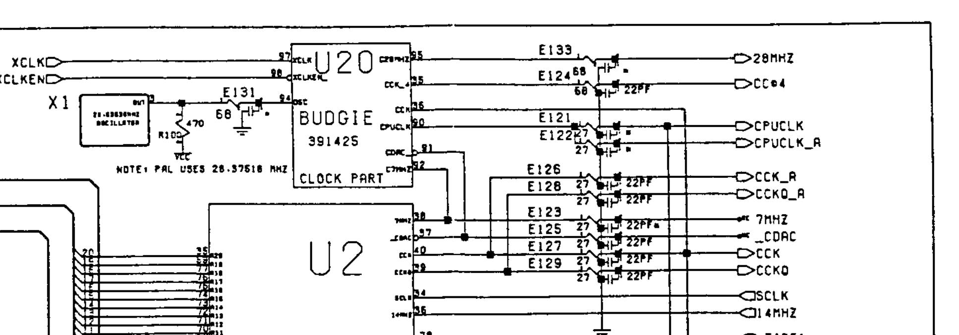
Detail of the "Channel Z" sheet of Commodore's Amiga 1200 main board schematic 364717 ("A1200 Rev 1->1D PCB", 1992). It shows the clock part of U20 (Budgie, 391425) and the clock pins of U2 (Alice, 8374), with the series resistors and 22 pF capacitors on each clock line: E121 and E122 on CPUCLK and CPUCLK_A, E126 and E128 on CCK_A and CCKQ_A, E123 on 7MHZ (Alice pin 38), E125 on _CDAC (Alice pin 37), and E127 and E129 on CCK and CCKQ. Several of the capacitors carry an asterisk.
Source
[edit | edit source]

Rendered from File:Commodore Amiga A1200 Schematics Rev 1-1D (1992).pdf, PDF page 6, at 400 dpi and cropped. The schematics are described at Amiga 1200 Schematics.
Author
[edit | edit source]

Commodore Business Machines.
Licence
[edit | edit source]

Copyright Commodore Business Machines. Hosted for preservation and repair reference, with the source cited.
File history
Click on a date/time to view the file as it appeared at that time.
| Date/Time | Thumbnail | Dimensions | User | Comment | |
|---|---|---|---|---|---|
| current | 11:37, 25 October 2026 | | 1,935 × 676 (174 KB) | Josh (talk | contribs) | Upload for Amiga repair guide |
You cannot overwrite this file.
File usage
The following page uses this file:
