

File:Amiga 1200 chip RAM and Budgie (Commodore schematic 364717).png

Summary
[edit | edit source]

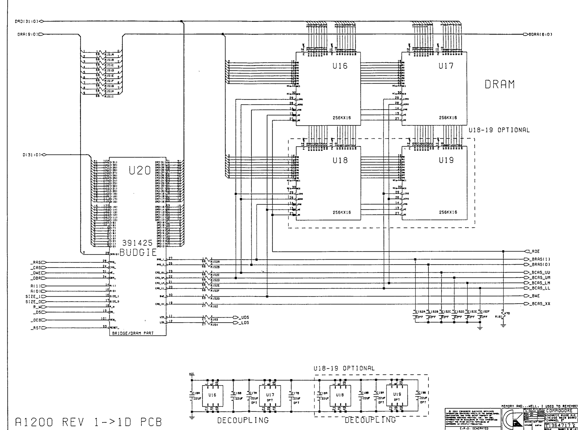
The DRAM sheet of Commodore's Amiga 1200 main board schematic 364717 (Rev. 1 to 1D, 1992): the chip RAM U16 and U17 and the optional U18 and U19 (256K × 16 each), driven by the bridge and DRAM part of U20 (Budgie, 391425) through the 68 Ω resistors R151A-R151I on the address lines and R152A-R152G on the RAS, CAS and write-enable lines, with the decoupling capacitors below.
Source
[edit | edit source]

Rendered from File:Commodore Amiga A1200 Schematics Rev 1-1D (1992).pdf, PDF page 7, at 300 dpi and cropped. The schematics are described at Amiga 1200 Schematics.
Author
[edit | edit source]

Commodore Business Machines.
Licence
[edit | edit source]

Copyright Commodore Business Machines. Hosted for preservation and repair reference, with the source cited.
File history
Click on a date/time to view the file as it appeared at that time.
| Date/Time | Thumbnail | Dimensions | User | Comment | |
|---|---|---|---|---|---|
| current | 11:37, 25 October 2026 | | 2,200 × 1,638 (847 KB) | Josh (talk | contribs) | Upload for Amiga repair guide |
You cannot overwrite this file.
File usage
The following page uses this file:
