

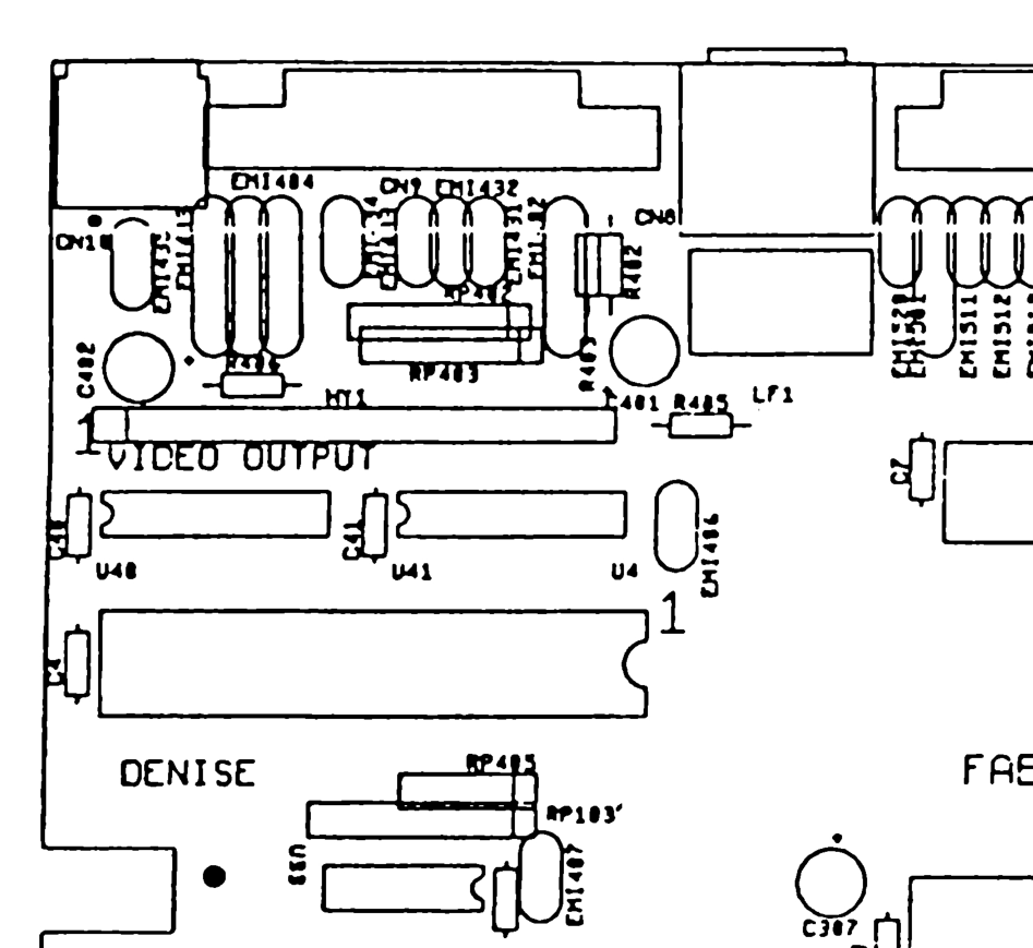
File:Amiga 500 Rev 5 board layout, video area (Commodore 312510).png
Size of this preview: 653 × 599 pixels. Other resolution: 947 × 869 pixels.

Original file (947 × 869 pixels, file size: 143 KB, MIME type: image/png)
Summary
[edit | edit source]

Detail of Commodore's component layout drawing "A500 Board Layout #312510, Rev. 5" (Service Manual A500, PN-314981-04, page 4-7): the left rear corner of the board marked "VIDEO OUTPUT", with the hybrid HY1, U40, U41, Denise (U4), R405, RP403, the EMI filters along the rear edge and the connector positions CN8, CN9 and CN10.
Source
[edit | edit source]

Rendered from File:Commodore Amiga A500 Service Manual 314981-04 (1990 Oct).pdf, PDF page 54 (manual page 4-7), at 300 dpi and cropped.
Author
[edit | edit source]

Commodore Business Machines.
Licence
[edit | edit source]

Copyright Commodore Business Machines. Hosted for preservation and repair reference, with the source cited.
File history
Click on a date/time to view the file as it appeared at that time.
| Date/Time | Thumbnail | Dimensions | User | Comment | |
|---|---|---|---|---|---|
| current | 10:46, 25 October 2026 | | 947 × 869 (143 KB) | Josh (talk | contribs) | Upload for Amiga repair guide |
You cannot overwrite this file.
File usage
The following page uses this file:
