

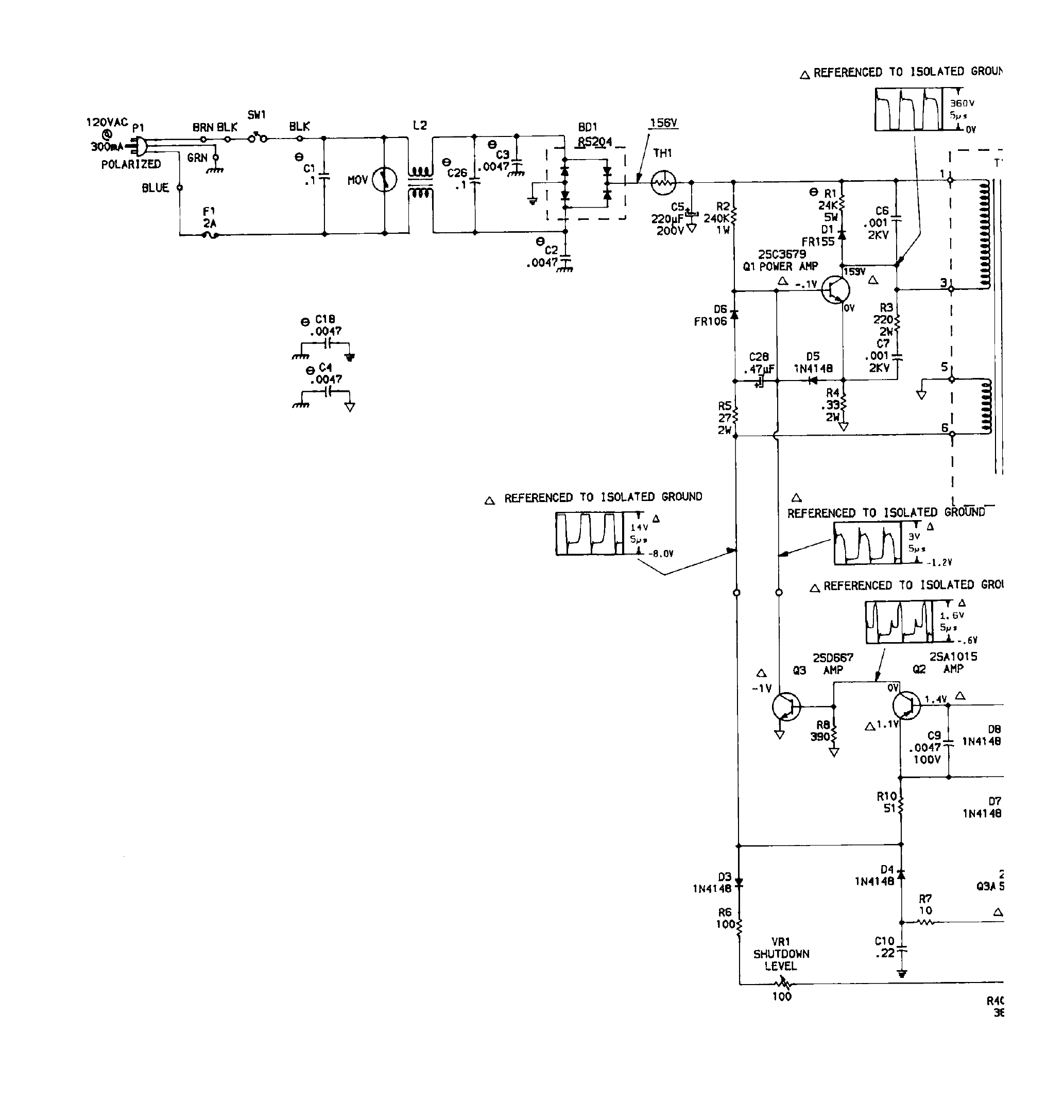
File:Amiga 500 power supply schematic, primary side (Sams Computerfacts CSCS26).png

Summary
[edit | edit source]

The primary side of the Amiga 500 power supply schematic in Howard W. Sams' Computerfacts CSCS26 (1988), printed page 6: 120 V AC input with fuse F1 (2 A), switch SW1, the line filter L2, MOV, the bridge rectifier BD1 (RS204), thermistor TH1, the 220 µF 200 V reservoir C5 marked 156 V, the switching transistor Q1 (2SC3679) with its snubber, Q2 (2SA1015), Q3 (2SD667), the shutdown level control VR1 and scope traces referenced to the isolated ground. The transformer T1 straddles the fold to the facing page.
Source
[edit | edit source]

Rendered from File:Sams Computerfacts CSCS26 Commodore Amiga A500.pdf, PDF page 10 (printed page 6), at 250 dpi and cropped.
Author
[edit | edit source]

Howard W. Sams & Co.
Licence
[edit | edit source]

Copyright Howard W. Sams & Co. (1988). Reproduced from the hosted Computerfacts folder for preservation and repair reference, with the source cited.
File history
Click on a date/time to view the file as it appeared at that time.
| Date/Time | Thumbnail | Dimensions | User | Comment | |
|---|---|---|---|---|---|
| current | 10:59, 25 October 2026 | | 2,066 × 2,175 (84 KB) | Josh (talk | contribs) | Upload for Amiga repair guide |
You cannot overwrite this file.
File usage
The following page uses this file:
