

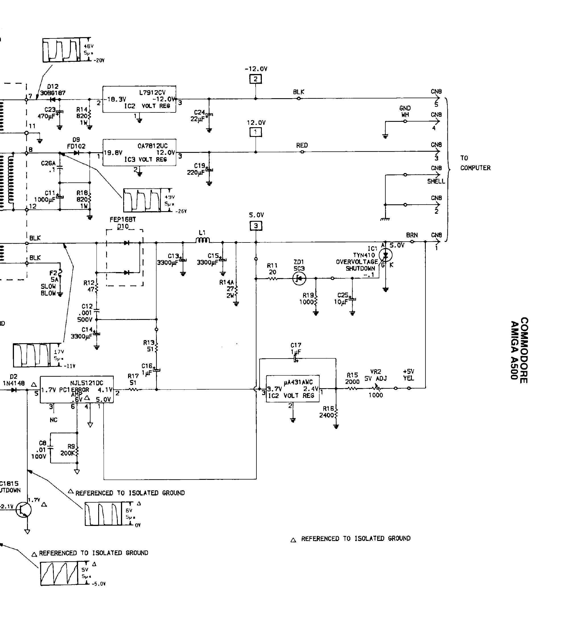
File:Amiga 500 power supply schematic, secondary side (Sams Computerfacts CSCS26).png

Summary
[edit | edit source]

The secondary side of the Amiga 500 power supply schematic in Howard W. Sams' Computerfacts CSCS26 (1988), printed page 35: the −12 V regulator (L7912CV) fed with −18.3 V through D12, the 12 V regulator IC3 fed with 19.8 V through D9, the 5 V rectifier D10 (FEP16BT) with F2 (5 A slow-blow), L1 and the 3300 µF filters C13-C15, the overvoltage shutdown SCR IC1 (TYN410) with ZD1, the error-amplifier optocoupler PC1, the shunt regulator IC2 (µA431AWC) with the 5 V adjust VR2, the shutdown transistor, and the output plug CN8 (pin 1 5 V brown, pin 3 12 V red, pin 5 −12 V black, pin 4 ground, pin 2 shell).
Source
[edit | edit source]

Rendered from File:Sams Computerfacts CSCS26 Commodore Amiga A500.pdf, PDF page 39 (printed page 35), at 250 dpi and cropped.
Author
[edit | edit source]

Howard W. Sams & Co.
Licence
[edit | edit source]

Copyright Howard W. Sams & Co. (1988). Reproduced from the hosted Computerfacts folder for preservation and repair reference, with the source cited.
File history
Click on a date/time to view the file as it appeared at that time.
| Date/Time | Thumbnail | Dimensions | User | Comment | |
|---|---|---|---|---|---|
| current | 10:59, 25 October 2026 | | 2,066 × 2,175 (98 KB) | Josh (talk | contribs) | Upload for Amiga repair guide |
You cannot overwrite this file.
File usage
The following page uses this file:
