

File:Amiga 500 service parts reference diagram (Commodore 314981-04 p. 4-1).png

Summary
[edit | edit source]

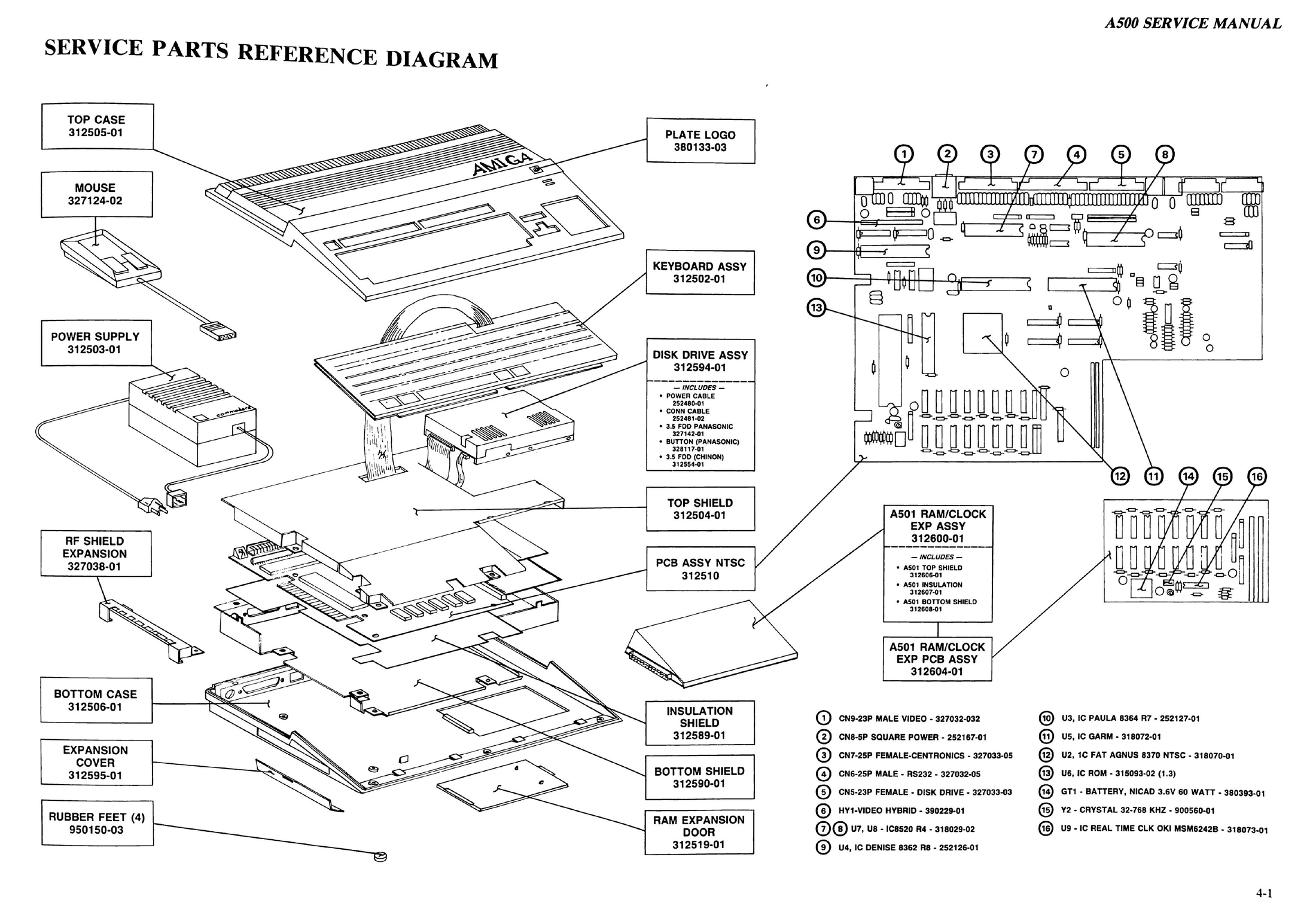
The service parts reference diagram from page 4-1 of Commodore's Service Manual A500 (PN-314981-04, October 1990). An exploded view of the Amiga 500 shows the top case, keyboard assembly, disk drive assembly, top shield, main board (PCB assembly 312510), insulation shield, bottom shield, bottom case, RAM expansion door, the A501 RAM/clock expansion, the power supply 312503-01 and the mouse, each with its Commodore part number, and a board outline keyed to sixteen major parts (connectors CN5-CN9, the video hybrid HY1, the CIAs U7 and U8, Denise, Paula, Gary, Agnus, the ROM, and the A501's battery, crystal and clock chip).
Source
[edit | edit source]

Rendered from File:Commodore Amiga A500 Service Manual 314981-04 (1990 Oct).pdf, PDF page 48 (manual page 4-1), at 250 dpi.
Author
[edit | edit source]

Commodore Business Machines.
Licence
[edit | edit source]

Copyright Commodore Business Machines. Hosted for preservation and repair reference, with the source cited.
File history
Click on a date/time to view the file as it appeared at that time.
| Date/Time | Thumbnail | Dimensions | User | Comment | |
|---|---|---|---|---|---|
| current | 10:36, 25 October 2026 | | 2,200 × 1,531 (1.34 MB) | Josh (talk | contribs) | Upload for Amiga repair guide |
You cannot overwrite this file.
File usage
The following page uses this file:
