

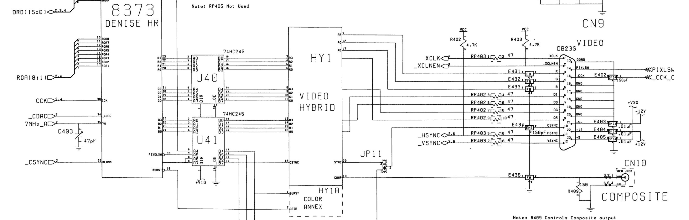
File:Amiga 500 video output circuit (Commodore schematic 312511-03 sheet 5).png

Summary
[edit | edit source]

Detail of Commodore schematic 312511-03, Rev. 6A/7, sheet 5 of 8, for the Amiga 500 main board (Service Manual A500, PN-314981-04, October 1990, page 5-14). It shows Denise (U4, 8373 Denise HR) with its digital colour outputs, the two 74HC245 buffers U40 and U41, the video hybrid HY1 with its optional colour annex HY1A, jumper JP11, the 47 Ω resistor packs RP402 and RP403 on the digital and sync lines, the filters E431-E435, the 23-pin RGB connector CN9 and the composite jack CN10 with R409 (150 Ω) and the note on R409 setting the composite level for the 390229-01 hybrid.
Source
[edit | edit source]

Rendered from File:Commodore Amiga A500 Service Manual 314981-04 (1990 Oct).pdf, PDF page 70 (manual page 5-14), at 300 dpi and cropped.
Author
[edit | edit source]

Commodore Business Machines.
Licence
[edit | edit source]

Copyright Commodore Business Machines. Hosted for preservation and repair reference, with the source cited.
File history
Click on a date/time to view the file as it appeared at that time.
| Date/Time | Thumbnail | Dimensions | User | Comment | |
|---|---|---|---|---|---|
| current | 10:46, 25 October 2026 | | 2,200 × 702 (493 KB) | Josh (talk | contribs) | Upload for Amiga repair guide |
You cannot overwrite this file.
File usage
The following page uses this file:
