

File:Amiga 600 power-up reset circuit (Commodore schematic 315987 sheet 9).png

Summary
[edit | edit source]

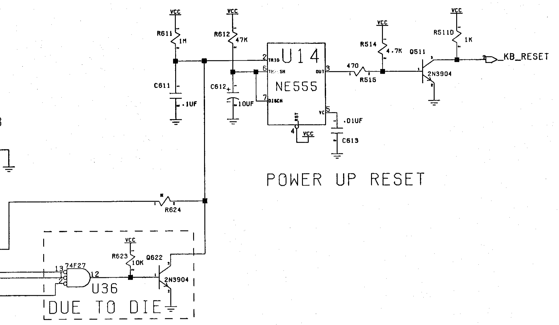
Detail of Commodore schematic 315987, Rev. C, sheet 9 of 13, for the Amiga 600 main board, from the A600 System Schematics (PN-400422-02, April 1992), printed page 5-9. It shows the power-up reset: U14 (NE555) with R611 (1 MΩ) and C611 (0.1 µF) on the trigger input pin 2, R612 (47 kΩ) and C612 (10 µF) on the threshold and discharge pins 6 and 7, C613 (0.01 µF) on pin 5, and the output pin 3 driving Q511 (2N3904) through R515 (470 Ω) to the _KB_RESET line. Below, U36 (74F27) and Q622 (2N3904) pull the same trigger node low from the keyboard tail; R624 is marked as not fitted in the parts list.
Source
[edit | edit source]

Rendered from File:Commodore Amiga A600 System Schematics 400422-02 (1992 Apr).pdf, PDF page 39 (printed page 5-9), at 300 dpi and cropped. The document is described at Amiga 600 System Schematics (400422-02).
Author
[edit | edit source]

Commodore Business Machines.
Licence
[edit | edit source]

Copyright Commodore Business Machines. Hosted for preservation and repair reference, with the source cited.
File history
Click on a date/time to view the file as it appeared at that time.
| Date/Time | Thumbnail | Dimensions | User | Comment | |
|---|---|---|---|---|---|
| current | 11:22, 25 October 2026 | | 1,838 × 1,070 (49 KB) | Josh (talk | contribs) | Upload for Amiga repair guide |
You cannot overwrite this file.
File usage
The following page uses this file:
