

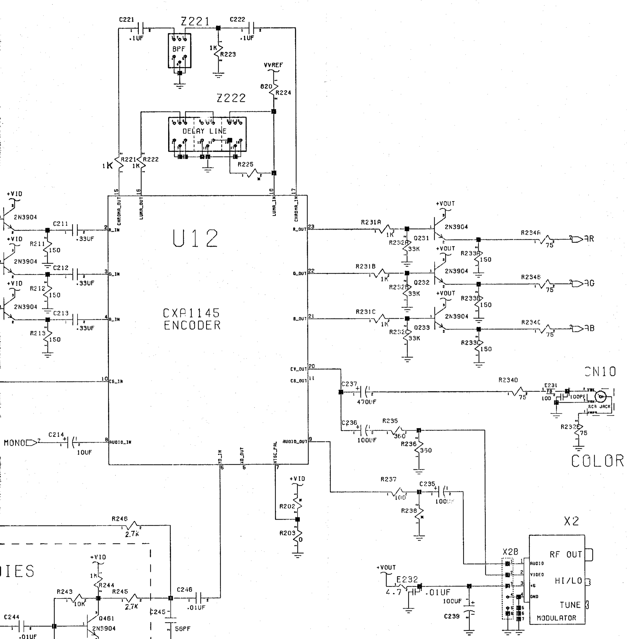
File:Amiga 600 video encoder circuit (Commodore schematic 315987 sheet 4).png

Summary
[edit | edit source]

Detail of Commodore schematic 315987, Rev. C, sheet 4 of 13, for the Amiga 600 main board (A600 System Schematics, PN-400422-02, printed page 5-4). It shows U12, the Sony CXA1145 encoder, with the band-pass filter Z221 between pins 15 and 17 and the delay line Z222 between pins 16 and 18; the RGB inputs on pins 2-4 through C211-C213; the RGB outputs on pins 21-23 buffered by Q231-Q233 (2N3904) and R234A-R234C (75 Ω) to the AR, AG and AB lines; the composite output on pin 20 through C237 (470 µF) and R234D to the RCA jack CN10; and the video and audio feeds to the RF modulator X2.
Source
[edit | edit source]

Rendered from File:Commodore Amiga A600 System Schematics 400422-02 (1992 Apr).pdf, PDF page 29 (printed page 5-4), at 300 dpi and cropped. The document is described at Amiga 600 System Schematics (400422-02).
Author
[edit | edit source]

Commodore Business Machines.
Licence
[edit | edit source]

Copyright Commodore Business Machines. Hosted for preservation and repair reference, with the source cited.
File history
Click on a date/time to view the file as it appeared at that time.
| Date/Time | Thumbnail | Dimensions | User | Comment | |
|---|---|---|---|---|---|
| current | 11:22, 25 October 2026 | | 2,200 × 2,244 (719 KB) | Josh (talk | contribs) | Upload for Amiga repair guide |
You cannot overwrite this file.
File usage
The following page uses this file:
