

File:Atari 1040ST 12 V converter U62 (Atari Benelux bulletin 7).png

Summary
[edit | edit source]

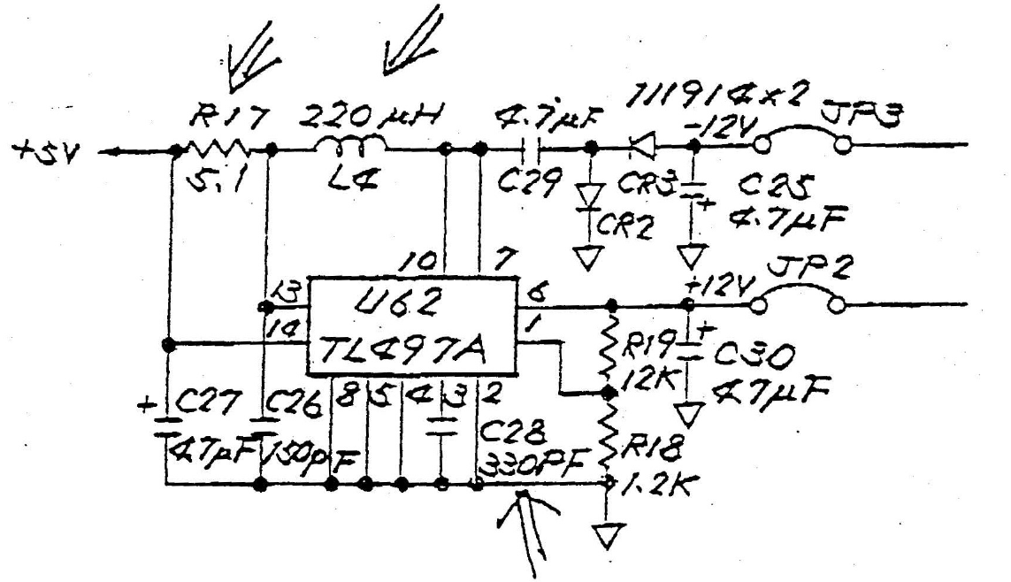
Drawing of the 12 V converter on the Atari 1040ST main board, from Atari Benelux's technical bulletin No. 7 (Information Technique No. 7, "sifflement dans le 1040"). It shows U62, a TL497A switching regulator, fed from +5 V through R17 and L4, with the timing capacitor C28, the feedback divider R19 (12 kΩ) and R18 (1.2 kΩ), the +12 V output to jumper JP2 and the −12 V output through C29, CR2, CR3 and C25 to jumper JP3. The arrows and the values for R17 (5.1 Ω), L4 (220 µH) and C28 (330 pF) mark the bulletin's modification. Cropped from page 1 of File:Atari Benelux technical bulletin 007 - 1040ST converter whistle.pdf.
Source
[edit | edit source]

File:Atari Benelux technical bulletin 007 - 1040ST converter whistle.pdf, from the Internet Archive item atari-benelux-techinfo-007-fre (retrieved 2026-10-25).
Author
[edit | edit source]

Atari (Benelux) B.V.
Licence
[edit | edit source]

Copyright Atari Corporation. Hosted for preservation and repair reference, with the source cited.
File history
Click on a date/time to view the file as it appeared at that time.
| Date/Time | Thumbnail | Dimensions | User | Comment | |
|---|---|---|---|---|---|
| current | 10:51, 25 October 2026 | | 1,143 × 658 (161 KB) | Josh (talk | contribs) | Crop of Atari Benelux bulletin 7 converter drawing |
You cannot overwrite this file.
File usage
The following page uses this file:
