

File:Atari 1050 serial interface U1 (Sams Computerfacts CD13 schematic).png

Summary
[edit | edit source]

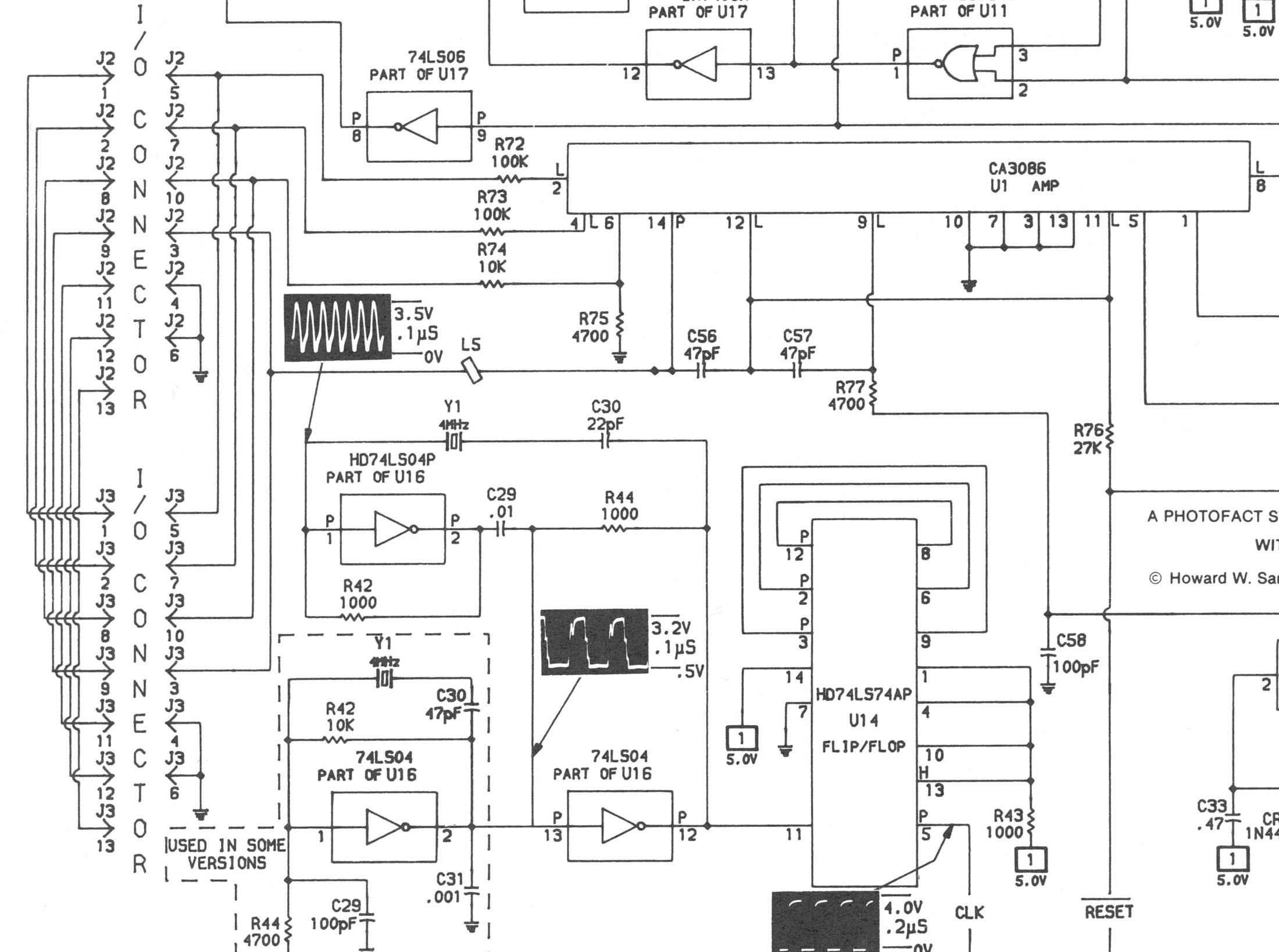
Serial bus section of the Sams schematic for the Atari 1050: the two I/O connectors J2 and J3 wired in parallel, the input resistors R72 (100k), R73 (100k), R74 (10k) and R75 (4700 ohms), the CA3086 transistor array U1, the data line to the computer through L5 with the waveform Sams measured there (3.5 V), C56, C57, R76 and R77. The 4 MHz clock oscillator (U16, Y1) and the 74LS74 U14 are also on this part of the sheet.
Source
[edit | edit source]

Howard W. Sams & Co., Computerfacts CD13, Atari Model 1050 Disk Drive (1987), hosted here as File:Sams Computerfacts CD13 Atari 1050 Disk Drive.pdf (Internet Archive item samscomputerfactstechnicalservicedataatarimodel1050diskdive1987sams), PDF page 3 (fold-out schematic, printed page 2). Cropped and downscaled for the wiki on 2026-10-25.
Author
[edit | edit source]

Howard W. Sams & Co.
Licence
[edit | edit source]

Copyright 1987 Howard W. Sams & Co. Used with credit for repair reference, not freely licensed.
File history
Click on a date/time to view the file as it appeared at that time.
| Date/Time | Thumbnail | Dimensions | User | Comment | |
|---|---|---|---|---|---|
| current | 21:38, 25 October 2026 | | 2,200 × 1,637 (592 KB) | Josh (talk | contribs) | Figure for an Atari 1050 repair guide |
You cannot overwrite this file.
File usage
The following page uses this file:
