

File:Atari 1050 serial interface U1 schematic (field service manual sheet 4).png

Summary
[edit | edit source]

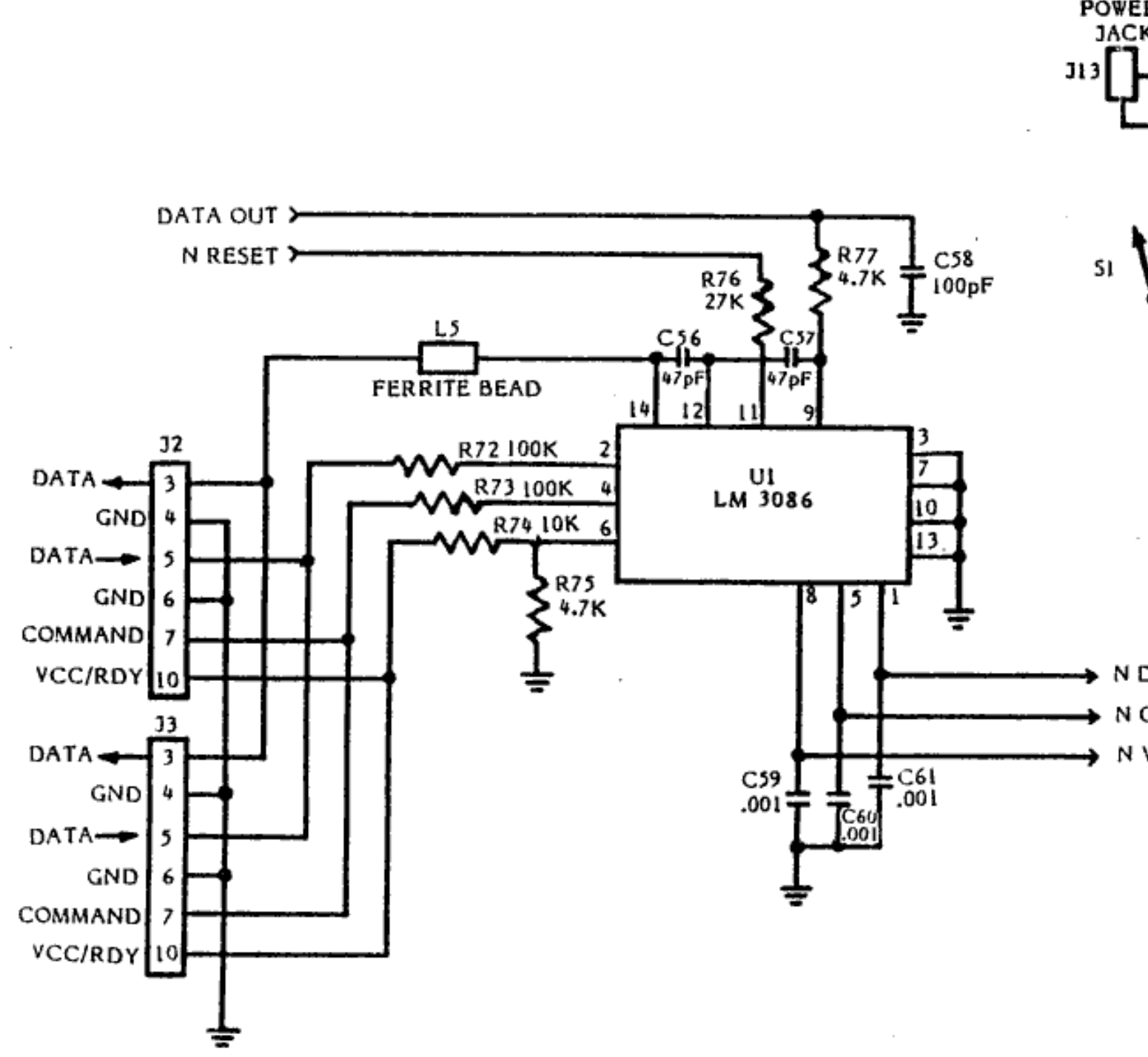
Serial bus interface of Atari's 1050 schematic, sheet 4 of 4 (Tandon): the two 13-pin SIO connectors J2 and J3, input resistors R72, R73, R74 and R75, the LM3086 transistor array U1, the data-out path through R76, R77, C56, C57 and the ferrite bead L5, and the outputs N DATA IN, N CMD and N VCC RDY to the PIA. The edge of the power-switch drawing appears at the top right. Cropped from the redrawn copy of the sheet in the rebuilt manual scan.
Source
[edit | edit source]

Atari, Inc., 1050 Disk Drive Field Service Manual (FD100330), hosted here as File:Atari 1050 Disk Drive Field Service Manual.pdf (rebuilt scan from Internet Archive item 1050FSMRebuiltAKH), PDF page 71 (redrawn copy of schematic sheet 4 of 4; Atari's original sheet is PDF page 66). Rendered and cropped for the wiki on 2026-10-25.
Author
[edit | edit source]

Atari, Inc.
Licence
[edit | edit source]

Copyright Atari, Inc. Hosted for preservation and repair reference, with the source cited.
File history
Click on a date/time to view the file as it appeared at that time.
| Date/Time | Thumbnail | Dimensions | User | Comment | |
|---|---|---|---|---|---|
| current | 19:50, 25 October 2026 | | 1,551 × 1,428 (144 KB) | Josh (talk | contribs) | Figure for an Atari 1050 repair guide |
You cannot overwrite this file.
File usage
The following page uses this file:
