

File:Atari 2600 channel 3 switchboard schematic (FSM figure 2-4).png
Size of this preview: 733 × 599 pixels. Other resolution: 1,590 × 1,300 pixels.

Original file (1,590 × 1,300 pixels, file size: 81 KB, MIME type: image/png)
Summary
[edit | edit source]

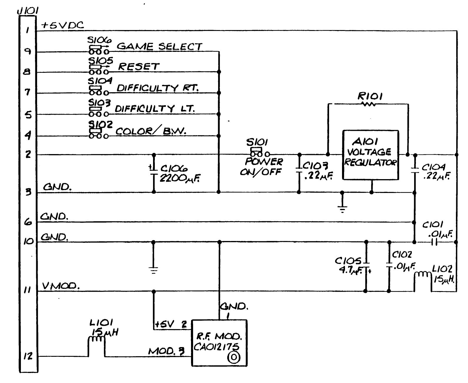
Figure 2-4, '2600 Channel 3 Switchboard Schematic', from Atari's Video Computer System Field Service Manual, Domestic Model 2600/2600A (FD100133 Rev. 02), page 2-7, rotated to read horizontally. It shows the 12-pin connector J101, the power switch S101, reservoir C106 (2200 uF), regulator A101 with R101 across it, capacitors C101 to C105, the console switches S102 to S106 and the RF modulator CA012175.
Source
[edit | edit source]

Rendered from File:Atari 2600 and 2600A Field Service Manual.pdf, PDF page 21.
Author
[edit | edit source]

Atari, Inc.
Licence
[edit | edit source]

Copyright Atari, Inc. Not freely licensed. Hosted for preservation and repair reference, with the source cited.
File history
Click on a date/time to view the file as it appeared at that time.
| Date/Time | Thumbnail | Dimensions | User | Comment | |
|---|---|---|---|---|---|
| current | 10:33, 25 October 2026 | | 1,590 × 1,300 (81 KB) | Josh (talk | contribs) | Upload for repair guide |
You cannot overwrite this file.
File usage
The following 2 pages use this file:
