

File:Atari 520ST RS-232 port (schematic C070231 sheet 1).png

Summary
[edit | edit source]

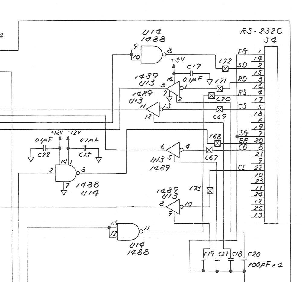
Crop of Atari's 520ST/260ST schematic, drawing C070231 revision M, sheet 1: the RS-232 port J4 (DB-25). The 1488 line driver U14, powered from +12 V (pin 14) and −12 V (pin 1), drives transmitted data (J4 pin 2, through L72), RTS (pin 4, through L70) and DTR (pin 20, through L68). The 1489 receiver U13 takes received data (pin 3, through L71), CTS (pin 5, L69), carrier detect (pin 8, L67) and ring indicator (pin 22, L73), with 100 pF capacitors C18–C21 on the lines. Pin 7 is signal ground and pin 1 frame ground. Cropped from File:Atari 520ST Schematic C070231.pdf; see Atari 520ST Schematic (C070231).
Source
[edit | edit source]

File:Atari 520ST Schematic C070231.pdf (rendered 2026-10-25).
Author
[edit | edit source]

Atari (Japan) Corporation.
Licence
[edit | edit source]

Copyright Atari Corporation. Hosted for preservation and repair reference, with the source cited.
File history
Click on a date/time to view the file as it appeared at that time.
| Date/Time | Thumbnail | Dimensions | User | Comment | |
|---|---|---|---|---|---|
| current | 11:23, 25 October 2026 | | 1,000 × 933 (125 KB) | Josh (talk | contribs) | Crop of Atari 520ST schematic C070231 for RS-232 repair guide |
You cannot overwrite this file.
File usage
The following page uses this file:
