

File:Atari 65XE keyboard matrix with J8 pins (Sobola schematic).png
Size of this preview: 800 × 534 pixels. Other resolutions: 2,560 × 1,709 pixels | 3,760 × 2,510 pixels.


Original file (3,760 × 2,510 pixels, file size: 21 KB, MIME type: image/png)
Summary
[edit | edit source]

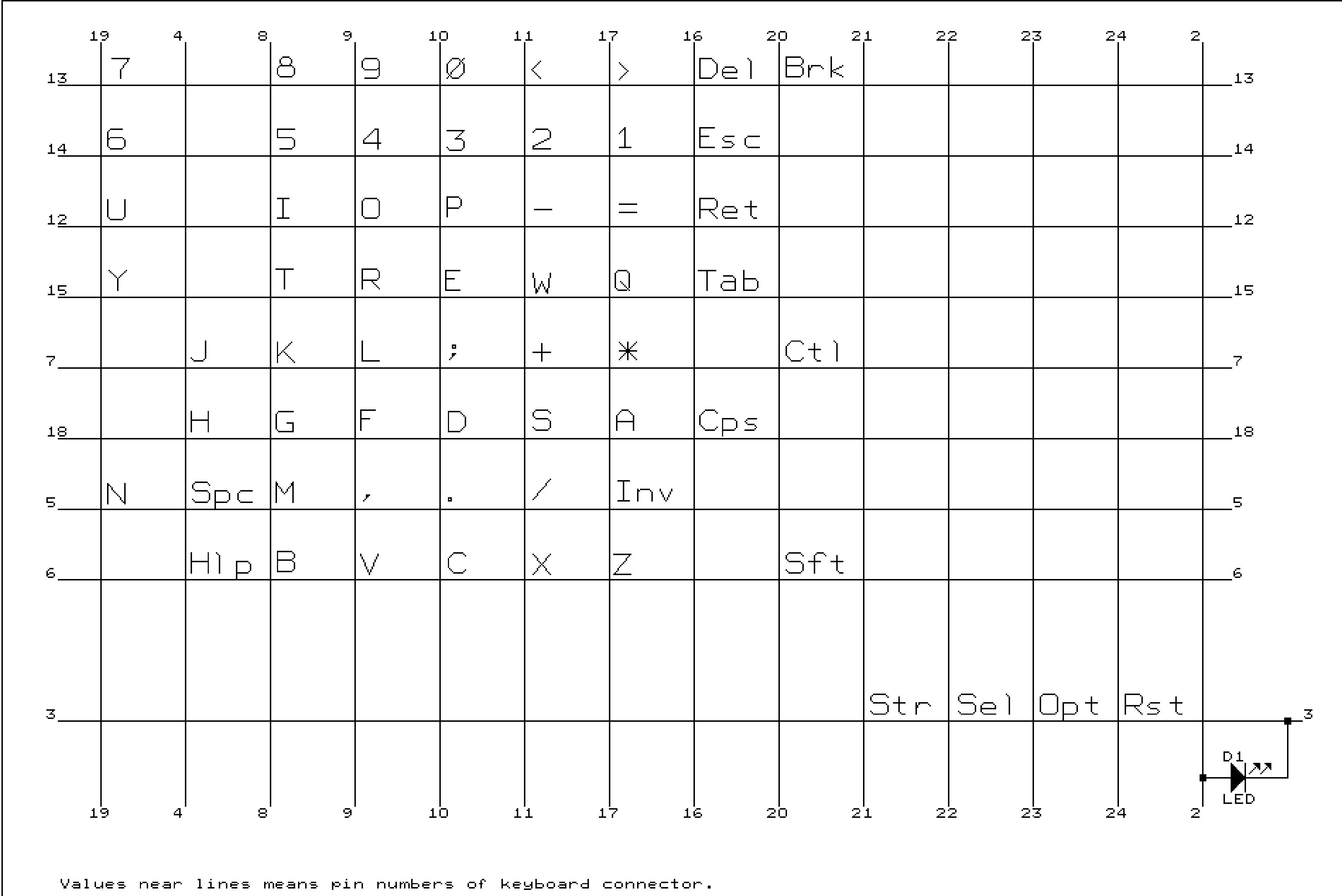
Sheet 7 of Jerzy Sobola's redrawn schematic of the Atari 65XE (dated 23 September 2003): the keyboard matrix, with each line numbered by its pin on the keyboard connector J8. Columns are J8 pins 19, 4, 8, 9, 10, 11, 17, 16, 20, 21, 22, 23, 24 and 2; rows are pins 13, 14, 12, 15, 7, 18, 5, 6 and 3. START, SELECT, OPTION and RESET sit on row 3, and the power LED D1 is between pins 2 and 3. A community redrawing, not an Atari document.
Source
[edit | edit source]

Cropped from File:ATARI65XE-SCHEMATIC.pdf, sheet 7 of 9, at the file's resolution.
Author
[edit | edit source]

Jerzy Sobola.
Licence
[edit | edit source]

No free licence is stated at the source. Used with credit as a repair reference.
File history
Click on a date/time to view the file as it appeared at that time.
| Date/Time | Thumbnail | Dimensions | User | Comment | |
|---|---|---|---|---|---|
| current | 11:58, 25 October 2026 | | 3,760 × 2,510 (21 KB) | Josh (talk | contribs) | Upload schematic detail for Atari 65XE repair guide |
You cannot overwrite this file.
File usage
The following page uses this file:
