

File:Atari 800XL SIO connector pin assignments (FD100740 figure 1-9).png

Summary
[edit | edit source]

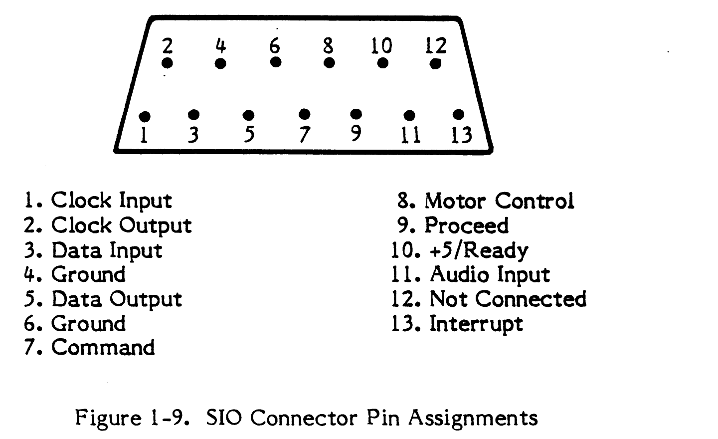
Figure 1-9, "SIO Connector Pin Assignments", from Atari's 800XL Computer Field Service Manual (FD100740 Rev. 01, February 1984), page 1-12: the 13-pin serial I/O socket with its pin numbering and the signal on each pin (1 clock input, 2 clock output, 3 data input, 4 ground, 5 data output, 6 ground, 7 command, 8 motor control, 9 proceed, 10 +5/ready, 11 audio input, 12 not connected, 13 interrupt).
Source
[edit | edit source]

Rendered from File:Atari 800XL Computer Field Service Manual FD100740 Rev 01.pdf, PDF page 20, at 300 dpi and cropped.
Author
[edit | edit source]

Atari, Inc.
Licence
[edit | edit source]

Copyright Atari, Inc. Hosted for preservation and repair reference, with the source cited.
File history
Click on a date/time to view the file as it appeared at that time.
| Date/Time | Thumbnail | Dimensions | User | Comment | |
|---|---|---|---|---|---|
| current | 11:22, 25 October 2026 | | 1,440 × 880 (46 KB) | Josh (talk | contribs) | Upload for repair guide |
You cannot overwrite this file.
File usage
The following page uses this file:
