

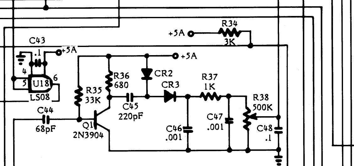
File:Atari 800XL colour adjust circuit Q1 R38 (FD100740 schematic).png
Size of this preview: 800 × 376 pixels. Other resolution: 1,128 × 530 pixels.

Original file (1,128 × 530 pixels, file size: 36 KB, MIME type: image/png)
Summary
[edit | edit source]

Detail of the 800XL schematic in Atari's 800XL Computer Field Service Manual (FD100740 Rev. 01, February 1984), section 5: the colour adjustment circuit, with a section of the 74LS08 U18 driving transistor Q1 (2N3904) through C44 (68 pF), R35, R36, C45 (220 pF), diodes CR2 and CR3, R37, C46, C47 and the 500 kΩ colour control R38 with C48, and R34 (3 kΩ) from +5A.
Source
[edit | edit source]

Rendered from File:Atari 800XL Computer Field Service Manual FD100740 Rev 01.pdf, PDF page 36, at 300 dpi and cropped.
Author
[edit | edit source]

Atari, Inc.
Licence
[edit | edit source]

Copyright Atari, Inc. Hosted for preservation and repair reference, with the source cited.
File history
Click on a date/time to view the file as it appeared at that time.
| Date/Time | Thumbnail | Dimensions | User | Comment | |
|---|---|---|---|---|---|
| current | 11:09, 25 October 2026 | | 1,128 × 530 (36 KB) | Josh (talk | contribs) | Upload for repair guide |
You cannot overwrite this file.
File usage
The following page uses this file:
