

File:Atari 850 serial port 1 buffers (service manual figure A11-1).png

Summary
[edit | edit source]

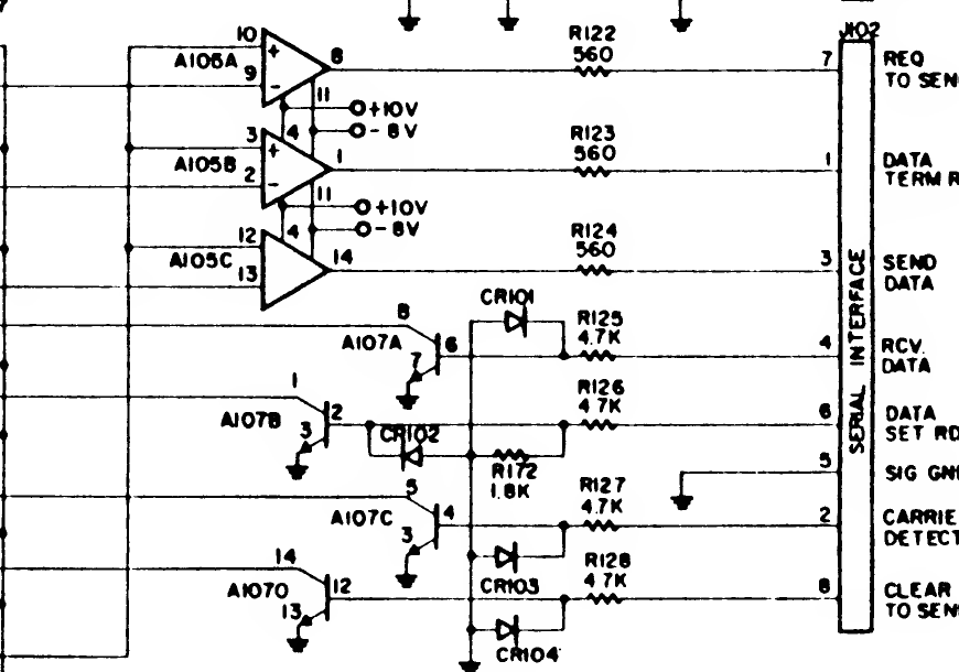
The serial port 1 section of Atari's 850 schematic: connector J102 (labelled SERIAL INTERFACE), the three LM349 driver sections for request to send, data terminal ready and send data with their 560 ohm resistors R122 to R124, and the four CA3086 receiver sections A107A to A107D for receive data, data set ready, carrier detect and clear to send, with R125 to R128, R172 and diodes CR101 to CR104.
Source
[edit | edit source]

Atari, Inc., 850 Interface Module Service Manual, CS 400/800-S004-B, April 1981, figure A11-1, "Schematic" (appendix 11, PDF page 86), hosted here as File:Atari 850 Interface Module Service Manual CS400-800-S004-B.pdf. Rendered at 300 dpi, rotated to read horizontally and cropped.
Author
[edit | edit source]

Atari, Inc.
Licence
[edit | edit source]

Copyright Atari, Inc. Hosted for preservation and repair reference, with the source cited.
File history
Click on a date/time to view the file as it appeared at that time.
| Date/Time | Thumbnail | Dimensions | User | Comment | |
|---|---|---|---|---|---|
| current | 17:37, 25 October 2026 | | 870 × 610 (57 KB) | Josh (talk | contribs) | Crop of Atari 850 schematic for serial port repair guide |
You cannot overwrite this file.
File usage
The following page uses this file:
