

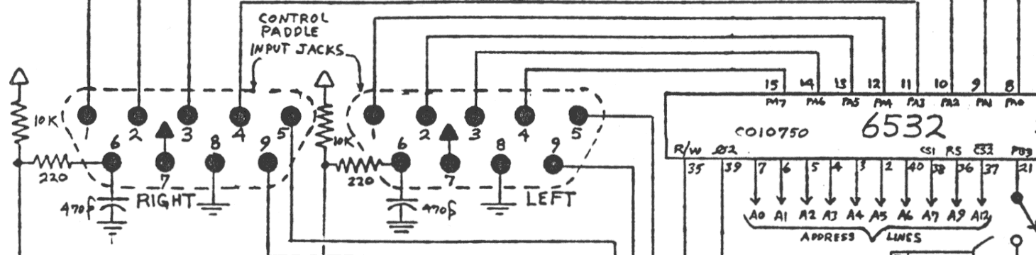
File:Atari CX-2600A schematic, controller ports and 6532.png
Size of this preview: 799 × 197 pixels. Other resolution: 1,460 × 360 pixels.

Original file (1,460 × 360 pixels, file size: 81 KB, MIME type: image/png)
Summary
[edit | edit source]

Crop of Atari's CX-2600A main board schematic (sheet 2 of 4, 30 May 1982) showing the right and left controller jacks: pins 1 to 4 wired to the 6532's port A (pins 8 to 15), pin 6 (trigger) with its 10K pull-up, 220 ohm series resistor and 470 pF capacitor, pin 7 at +5 V, pin 8 at ground and pins 5 and 9 to the paddle inputs.
Source
[edit | edit source]

Cropped from File:Schematic Atari2600A 2000.png, hosted on this wiki.

Author
[edit | edit source]

Atari, Inc.
Licence
[edit | edit source]

Copyright Atari, Inc. Not freely licensed. Hosted for preservation and repair reference, with the source cited.
File history
Click on a date/time to view the file as it appeared at that time.
| Date/Time | Thumbnail | Dimensions | User | Comment | |
|---|---|---|---|---|---|
| current | 11:05, 25 October 2026 | | 1,460 × 360 (81 KB) | Josh (talk | contribs) | Upload for repair guide |
You cannot overwrite this file.
File usage
The following page uses this file:
