

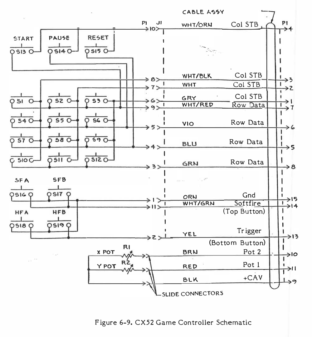
File:Atari CX52 controller schematic (FSM figure 6-9).png
Size of this preview: 555 × 599 pixels. Other resolution: 1,000 × 1,080 pixels.

Original file (1,000 × 1,080 pixels, file size: 369 KB, MIME type: image/png)
Summary
[edit | edit source]

Figure 6-9 of Atari's CX5200 field service manual: the CX52 controller schematic, with the keypad switches S1 to S12, START, PAUSE and RESET (S13 to S15), the top and bottom fire buttons (S16 to S19), the X and Y pots and the cable colours to the 15-pin plug P1.
Source
[edit | edit source]

Rendered with pdftoppm from the Atari CX5200 Field Service Manual (PDF), Atari, Inc., FD100127 Rev. 4, July 1983, PDF page 125 (manual p. 6-13), and cropped to the figure.
Author
[edit | edit source]

Atari, Inc.
Licence
[edit | edit source]

Copyright Atari, Inc. Not freely licensed. Hosted for preservation and repair reference, with the source cited.
File history
Click on a date/time to view the file as it appeared at that time.
| Date/Time | Thumbnail | Dimensions | User | Comment | |
|---|---|---|---|---|---|
| current | 11:36, 25 October 2026 | | 1,000 × 1,080 (369 KB) | Josh (talk | contribs) | Upload for repair guide |
You cannot overwrite this file.
File usage
The following page uses this file:
