

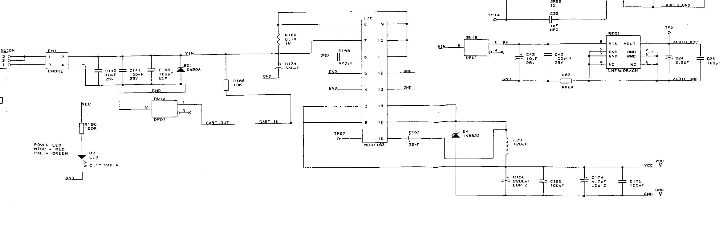
File:Atari Jaguar schematic, power input, U38 and REG1.png

Summary
[edit | edit source]

Crop of Atari's Jaguar console schematic, document 500162 Rev. 5.3 (21 September 1993), showing the power section: the adaptor socket PSUCON, choke CH1, C142, C141, C140 and the suppressor SD1 (SA20A) on VIN; the power switch halves SW1A (cartridge loop, CART_OUT) and SW1B (9 V to the audio regulator); R166 (10K) pulling CART_IN up to VIN; the MC34163 regulator U38 with R169 (0.1 ohm, 1 W), C134 (330 uF), C168 (470 pF), C167 (22 nF), TP87, D4 (1N5822), L29 (120 uH), C150 (2200 uF, low Z), C159, C174 (4.7 uF, low Z) and C175 on VCC; the LM78L05ACM audio regulator REG1 with C43, C40, R63, C24 and C35 and the test point TP6 on AUDIO_VCC; and the power LED D3 with R126 (150 ohm).
Source
[edit | edit source]

Rendered at 200 dpi with pdftoppm from File:Atari Jaguar Console Schematic 500162 Rev 5.3.pdf, hosted on this wiki, and cropped.
Author
[edit | edit source]

Atari Corporation
Licence
[edit | edit source]

Copyright Atari Corporation. Not freely licensed. Hosted for preservation and repair reference, with the source cited.
File history
Click on a date/time to view the file as it appeared at that time.
| Date/Time | Thumbnail | Dimensions | User | Comment | |
|---|---|---|---|---|---|
| current | 12:01, 25 October 2026 | | 2,360 × 730 (103 KB) | Josh (talk | contribs) | Upload for repair guide |
You cannot overwrite this file.
File usage
The following page uses this file:
