

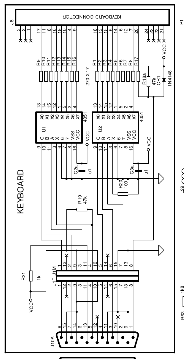
File:Atari XE Game System keyboard unit schematic (JER redraw).png

Summary
[edit | edit source]

The keyboard section of JER/Eightbitter's redrawn schematic of the XE Game System (figure 2-13, "XE-System Assembly C100417"): the membrane connector J8 with its pin numbers (pins 1 to 3 and 21 to 24 marked not connected), the seventeen 270 ohm resistors R1 to R17, R18a (47k) and CR1 (1N4148), the two 4051 multiplexers U1 and U2 with C2a and C3a (0.1 uF), R19 (47k), R20 (100 ohm) and R21 (1k), the internal connector J1F/J1M and the 15-pin plug J10A on the keyboard cable, with the console's socket J10 below it.
Source
[edit | edit source]

Rendered at 600 dpi with pdftoppm from page 32 of File:Atari 130XE Field Service Manual.pdf (130XE Personal Computer Field Service Manual, a 2016 reconstruction by JER/Eightbitter, not an Atari publication), hosted on this wiki, and cropped.
Author
[edit | edit source]

JER/Eightbitter (redrawing)
Licence
[edit | edit source]

Not stated at the source. Hosted for repair reference, with the source cited.
File history
Click on a date/time to view the file as it appeared at that time.
| Date/Time | Thumbnail | Dimensions | User | Comment | |
|---|---|---|---|---|---|
| current | 12:18, 25 October 2026 | | 640 × 1,250 (29 KB) | Josh (talk | contribs) | Upload for repair guide |
You cannot overwrite this file.
File usage
The following page uses this file:
