

File:Bipolar transistor as two diodes for meter testing (diagram).png

Summary
[edit | edit source]

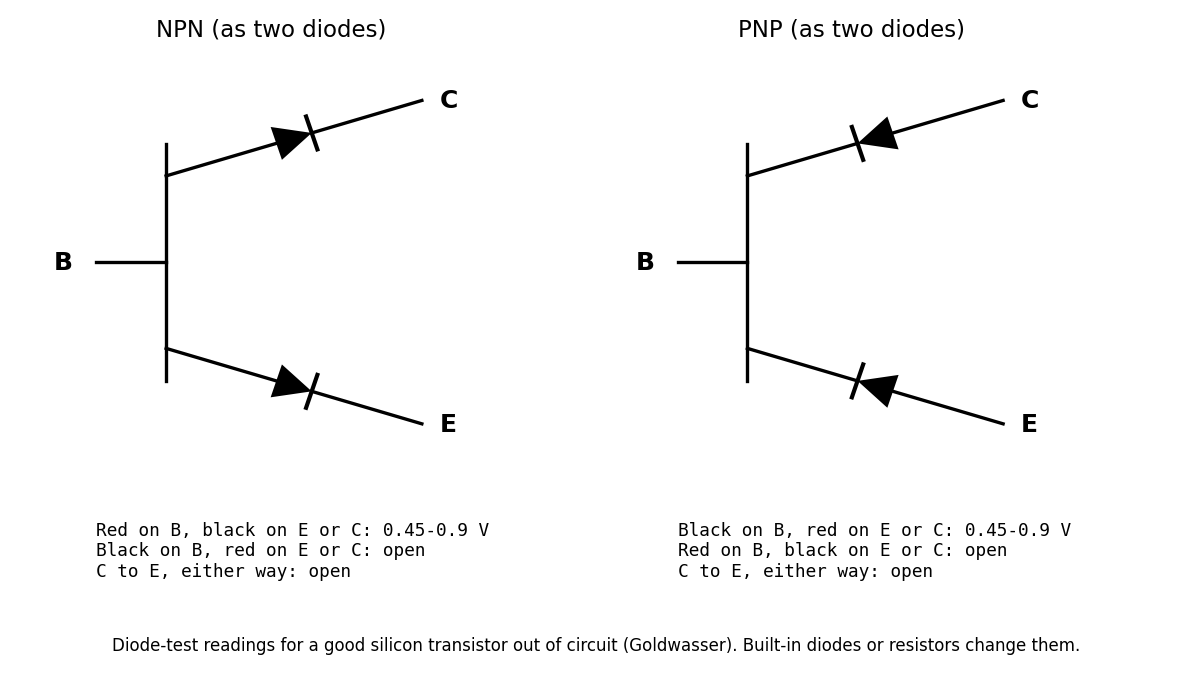
Diagram of an NPN and a PNP bipolar transistor drawn as two diodes joined at the base, with the multimeter diode-test readings for a good silicon transistor out of circuit: 0.45 to 0.9 V for each base junction in the forward direction, open in reverse, and open from collector to emitter both ways. Used on Testing Diodes, Transistors and Regulators.
Source
[edit | edit source]

Drawn for this wiki in October 2026 from Samuel M. Goldwasser, "Testing Semiconductor Devices with a VOM or DMM", version 2.45, 19 November 2006, sections "Transistor Testing Methodology" and "Testing with a (Digital) DMM".
Author
[edit | edit source]

RetroTechCollection wiki.
Licence
[edit | edit source]

Released under CC BY-SA 4.0 (https://creativecommons.org/licenses/by-sa/4.0/).
File history
Click on a date/time to view the file as it appeared at that time.
| Date/Time | Thumbnail | Dimensions | User | Comment | |
|---|---|---|---|---|---|
| current | 14:59, 25 October 2026 | | 1,192 × 676 (60 KB) | Josh (talk | contribs) | Upload for repair-technique page |
You cannot overwrite this file.
File usage
The following page uses this file:
