

File:Canon V-20 power supply circuit diagram.png

Summary
[edit | edit source]

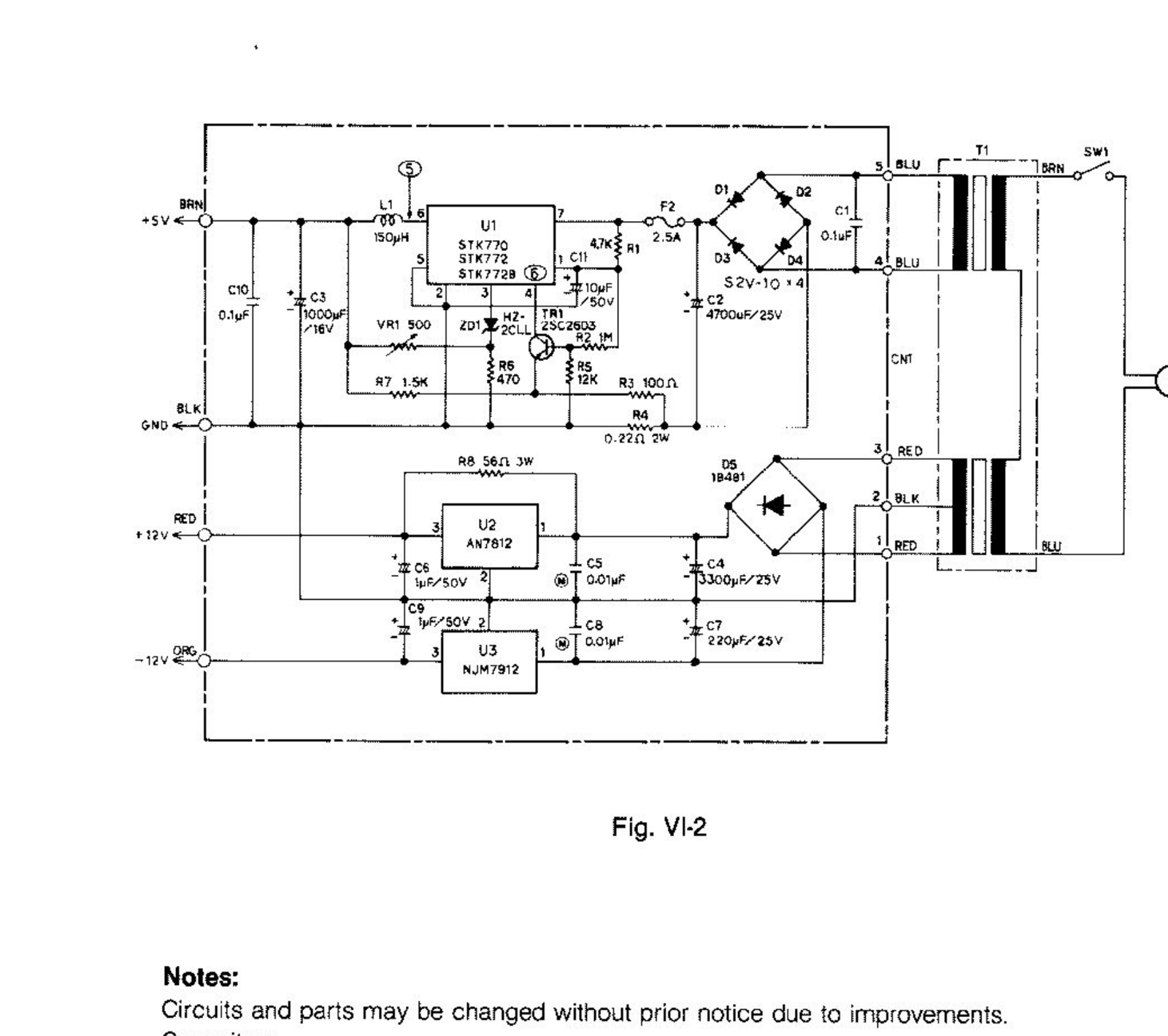
Fig. VI-2 from the Canon V-20 Service Manual, "Power supply section circuit diagram": transformer T1 and switch SW1; bridge D1 to D4 (S2V-10), fuse F2 (2.5 A), reservoir C2 (4700 µF, 25 V), STK770-series switching regulator U1 with L1 (150 µH), VR1 (500 Ω) and output capacitor C3 (1000 µF, 16 V) for +5 V; bridge D5 (1B4B1), C4 (3300 µF, 25 V) and AN7812 (U2) for +12 V; C7 (220 µF, 25 V on this diagram) and NJM7912 (U3) for −12 V; output wires brown +5 V, red +12 V, orange −12 V, black ground. Rendered at 300 dpi and cropped.
Source
[edit | edit source]

Rendered from the Canon V-20 Service Manual, Internet Archive item canonv20sm, https://archive.org/details/canonv20sm (uploaded by [email protected] on 26 October 2018; the PDF notes "Scanned by abuur, converted to pdf by HansO, 2009"). Retrieved 2026-10-21. Hosted here as File:Canon V-20 Service Manual.pdf.
Author
[edit | edit source]

Canon Inc.
Licence
[edit | edit source]

Copyright Canon Inc. Hosted for preservation and repair reference, with the source cited.
File history
Click on a date/time to view the file as it appeared at that time.
| Date/Time | Thumbnail | Dimensions | User | Comment | |
|---|---|---|---|---|---|
| current | 13:13, 21 October 2026 | | 1,600 × 1,420 (519 KB) | Josh (talk | contribs) | Upload for the Canon V-20 pages |
You cannot overwrite this file.
File usage
The following 3 pages use this file:
