

File:Coleco Adam interconnect board schematic 41840 Rev F.png

Summary
[edit | edit source]

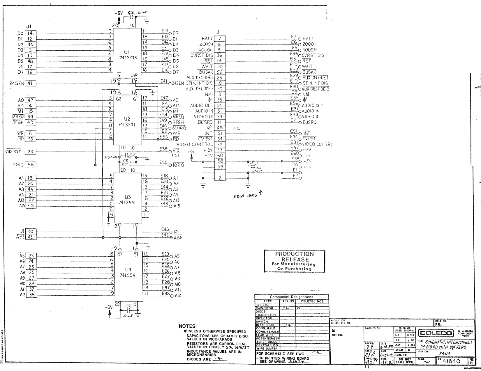
Coleco drawing 41840, revision F, "Schematic, interconnect P.C. board with buffers", drawn 14 June 1983, "used on 2404": the board that joins the Adam memory and I/O board to the ColecoVision's expansion connector in Expansion Module #3. U1 74LS245 data buffer; U2, U3 and U4 74LS541 address and control buffers; the 60-way edge connection J1 with +12 V on pin 57, −5 V on pin 60, +5 V on pins 58 and 59 and ground on pins 1 and 2; C2, 10 µF tantalum, across +5 V; C3 to C6, 0.01 µF; C1 deleted. Rendered at 150 dpi.
Source
[edit | edit source]

Rendered from File:Coleco Adam Schematics.pdf, sheet 4. The same drawing at revision E is appendix 4.3 of File:Coleco Adam Technical Reference Manual (Preliminary Release).pdf.
Author
[edit | edit source]

Coleco Industries, Inc.
Licence
[edit | edit source]

Copyright Coleco Industries, Inc. Reproduced from the hosted schematic set for repair reference.
File history
Click on a date/time to view the file as it appeared at that time.
| Date/Time | Thumbnail | Dimensions | User | Comment | |
|---|---|---|---|---|---|
| current | 14:12, 19 October 2026 | | 1,651 × 1,275 (186 KB) | Josh (talk | contribs) | Upload Coleco Adam interconnect board schematic 41840 Rev F with source and licence |
You cannot overwrite this file.
File usage
The following 2 pages use this file:
