

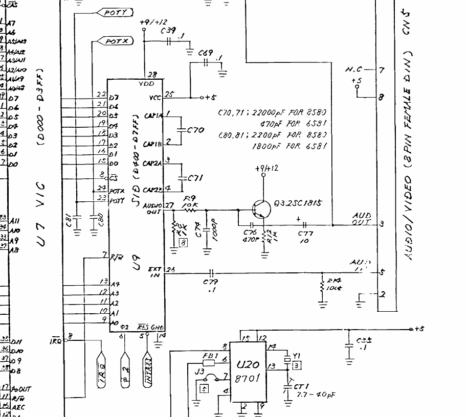
File:Commodore 64C E board SID circuit (schematic 252312).png

Summary
[edit | edit source]

Detail of Commodore schematic 252312 for the Commodore 64C E board (assembly 250469): the SID at U9 with filter capacitors C70 and C71, POT capacitors C80 and C81, the audio output through R9 and R8 (note 8) to buffer Q3, the external audio input via C79, and Commodore's note "C70,71: 22000pF for 8580, 470pF for 6581; C80,81: 2200pF for 8580, 1800pF for 6581". The 8701 clock generator U20 is at the bottom.
Source
[edit | edit source]

Rendered from File:Commodore 64 - 64C Service Manual.pdf, PDF page 52 (manual page 42, E schematic 252312), at 200 dpi and cropped.
Author
[edit | edit source]

Commodore Business Machines.
Licence
[edit | edit source]

Copyright Commodore Business Machines. Hosted for preservation and repair reference, with the source cited.
File history
Click on a date/time to view the file as it appeared at that time.
| Date/Time | Thumbnail | Dimensions | User | Comment | |
|---|---|---|---|---|---|
| current | 09:19, 25 October 2026 | | 915 × 816 (81 KB) | Josh (talk | contribs) | Upload for Commodore 64C SID Replacement guide |
You cannot overwrite this file.
File usage
The following page uses this file:
