

File:Commodore 64C E board SID supply Q5 CR7 (schematic 252312).png

Summary
[edit | edit source]

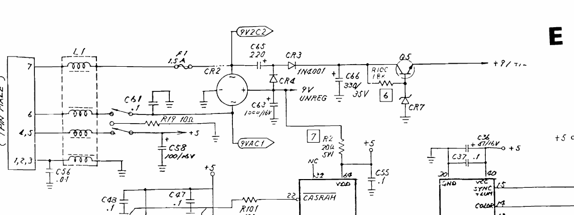
Detail of Commodore schematic 252312 for the Commodore 64C E board (assembly 250469): the power input CN7 with line filter L1, fuse F1 (1.5 A), the power switch, C58 and R19, bridge rectifier CR2 with reservoir C63 (9 V unregulated), and the SID supply formed by C65, CR3, CR4, C66, R100, transistor Q5 and zener CR7 (note 6), giving the "+9/+12" output.
Source
[edit | edit source]

Rendered from File:Commodore 64 - 64C Service Manual.pdf, PDF page 52 (manual page 42, E schematic 252312), at 200 dpi and cropped.
Author
[edit | edit source]

Commodore Business Machines.
Licence
[edit | edit source]

Copyright Commodore Business Machines. Hosted for preservation and repair reference, with the source cited.
File history
Click on a date/time to view the file as it appeared at that time.
| Date/Time | Thumbnail | Dimensions | User | Comment | |
|---|---|---|---|---|---|
| current | 09:19, 25 October 2026 | | 1,119 × 419 (43 KB) | Josh (talk | contribs) | Upload for Commodore 64C SID Replacement guide |
You cannot overwrite this file.
File usage
The following page uses this file:
