

File:Commodore 64C E board schematic 252312 notes.png
Summary
[edit | edit source]

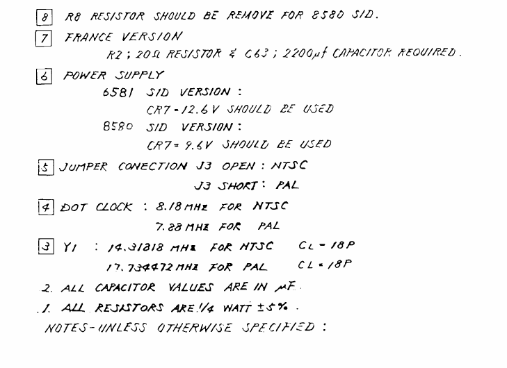
Notes 1 to 8 from Commodore schematic 252312 for the Commodore 64C E board: R8 removed for the 8580 SID (8); the French version's 20 Ω resistor at R2 and 2200 µF capacitor at C63 (7); CR7 12.6 V for the 6581 and 9.6 V for the 8580 (6); jumper J3 open for NTSC and shorted for PAL (5); dot clock and Y1 crystal frequencies (4, 3); and the general notes on units and resistor ratings.
Source
[edit | edit source]

Rendered from File:Commodore 64 - 64C Service Manual.pdf, PDF page 52 (manual page 42, E schematic 252312), at 200 dpi and cropped.
Author
[edit | edit source]

Commodore Business Machines.
Licence
[edit | edit source]

Copyright Commodore Business Machines. Hosted for preservation and repair reference, with the source cited.
File history
Click on a date/time to view the file as it appeared at that time.
| Date/Time | Thumbnail | Dimensions | User | Comment | |
|---|---|---|---|---|---|
| current | 09:20, 25 October 2026 | | 729 × 530 (35 KB) | Josh (talk | contribs) | Wider crop to include the note numbers |
| 09:19, 25 October 2026 | 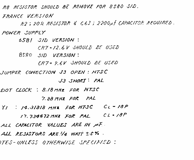 | 644 × 530 (32 KB) | Josh (talk | contribs) | Upload for Commodore 64C SID Replacement guide |
You cannot overwrite this file.
File usage
The following page uses this file:
