

File:Commodore 64 250407 board power section VR1 VR2 CR4 F1.jpg

Summary
[edit | edit source]

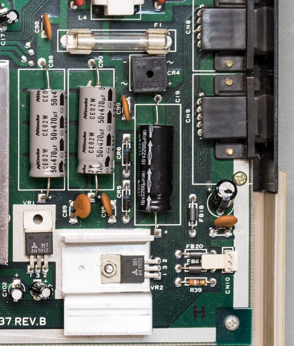
Detail of a Commodore 64 main board, assembly 250407 Rev. B (artwork 251137 Rev. B), showing the power section: fuse F1 in its clips, bridge rectifier CR4 (S2VB), C88 and C90 (Nitsuko 470 µF 50 V axial), C19 (2200 µF 16 V), diodes CR5 and CR6, VR1 (AN7812) and VR2 (AN7805) bolted to an aluminium heat sink, with the pin numbers 1, 3 and 2 printed beside each regulator, and the control ports CN8 and CN9 at the right.
Source
[edit | edit source]

Cropped from Wikimedia Commons, File:0430 - C64 Mainboard ASSY250407 RevB.jpg (retrieved 2026-10-25).

Author
[edit | edit source]

Sven.petersen, via Wikimedia Commons
Licence
[edit | edit source]

CC BY-SA 4.0. This crop is released under the same licence.
File history
Click on a date/time to view the file as it appeared at that time.
| Date/Time | Thumbnail | Dimensions | User | Comment | |
|---|---|---|---|---|---|
| current | 09:14, 25 October 2026 | | 960 × 1,128 (335 KB) | Josh (talk | contribs) | Upload for Commodore 64 Voltage Regulator Replacement guide |
You cannot overwrite this file.
File usage
The following page uses this file:
