

File:Crimp terminal anatomy diagram.png
Summary
[edit | edit source]

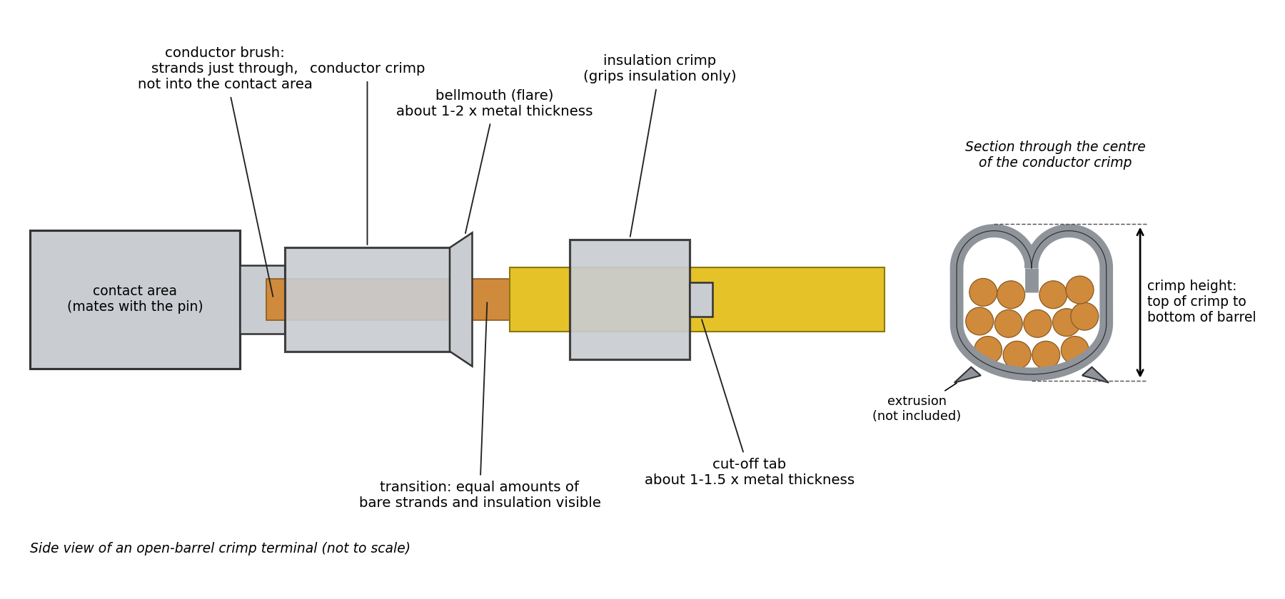
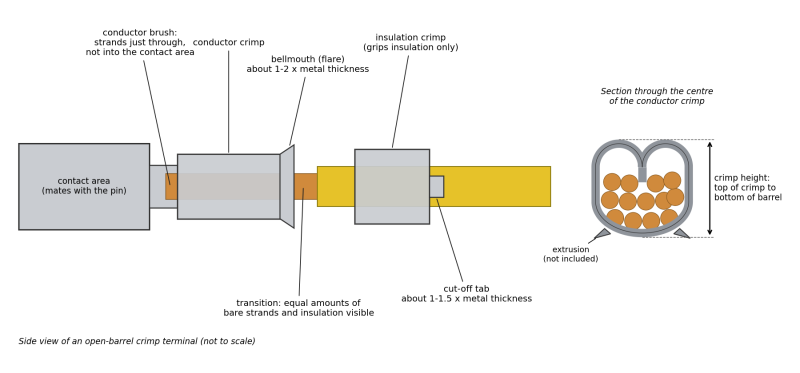
Diagram of an open-barrel crimp terminal: a side view naming the contact area, conductor brush, conductor crimp, bellmouth, transition, insulation crimp and cut-off tab, and a section through the centre of the conductor crimp showing where crimp height is measured (from the top of the crimp to the bottom of the barrel, excluding the extrusions). Not to scale.
Source
[edit | edit source]

Drawn for this wiki in October 2026 from the definitions in Molex, Quality Crimping Handbook, order no. 63800-0029 (document TM-638000029, revision D, 2009), section 4: bellmouth about 1 to 2 times the terminal material thickness, cut-off tab about 1.0 to 1.5 times, conductor brush not into the contact area, equal amounts of strands and insulation visible in the transition, crimp height measured without the extrusions. Used on Connector Pin Replacement and Crimping.
Author
[edit | edit source]

RetroTechCollection wiki.
Licence
[edit | edit source]

Released under CC BY-SA 4.0 (https://creativecommons.org/licenses/by-sa/4.0/). The facts shown are Molex's.
File history
Click on a date/time to view the file as it appeared at that time.
| Date/Time | Thumbnail | Dimensions | User | Comment | |
|---|---|---|---|---|---|
| current | 14:41, 25 October 2026 | | 1,800 × 840 (138 KB) | Josh (talk | contribs) | Upload diagram drawn for the repair-technique pages |
You cannot overwrite this file.
File usage
The following page uses this file:
