

File:Heat-seal connector cross-section diagram.png
Summary
[edit | edit source]

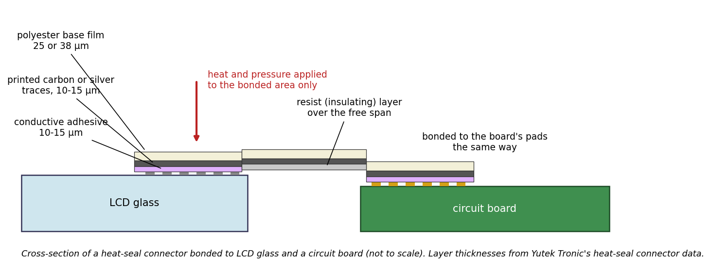
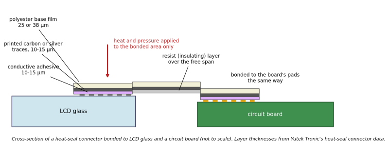
Diagram of a heat-seal connector (HSC) in cross-section, bonded at one end to the electrodes on an LCD's glass and at the other to the pads of a circuit board: polyester base film, printed carbon or silver traces, conductive adhesive at the bonded ends, and an insulating resist layer over the free span. The arrow marks where heat and pressure are applied. Not to scale.
Source
[edit | edit source]

Drawn for this wiki in October 2026. Layer structure and thicknesses (polyester base film 25 or 38 µm; carbon, silver or mixed conductive paste 10 to 15 µm; conductive adhesive 10 to 15 µm; resist layer) from Yutek Tronic Inc., Heat Seal Connector product data, "Structure of Product", p. 4, as hosted by Orient Display at https://www.orientdisplay.com/wp-content/uploads/2022/10/Heatseal.pdf (retrieved 2026-10-25). Used on Ribbon and Flex Cable Repair.
Author
[edit | edit source]

RetroTechCollection wiki.
Licence
[edit | edit source]

Released under CC BY-SA 4.0 (https://creativecommons.org/licenses/by-sa/4.0/). The facts shown are Yutek Tronic's.
File history
Click on a date/time to view the file as it appeared at that time.
| Date/Time | Thumbnail | Dimensions | User | Comment | |
|---|---|---|---|---|---|
| current | 14:54, 25 October 2026 | | 1,462 × 561 (77 KB) | Josh (talk | contribs) | Upload diagram drawn for the repair-technique pages |
You cannot overwrite this file.
File usage
The following page uses this file:
