

File:Linear regulator and switching module pinouts (diagram).png

Summary
[edit | edit source]

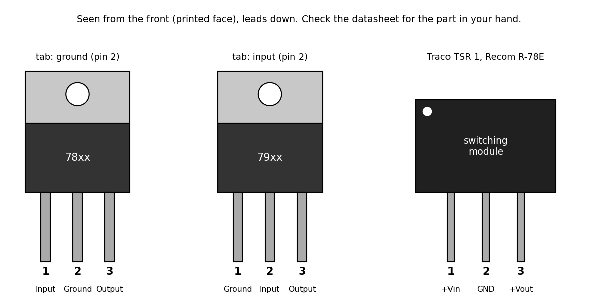
Diagram of the pin connections of a 78xx positive regulator (1 input, 2 ground, 3 output, tab at ground) and a 79xx negative regulator (1 ground, 2 input, 3 output, tab at input) in TO-220 packages, and of a Traco Power TSR 1 or RECOM R-78E switching module (1 +Vin, 2 GND, 3 +Vout), seen from the front with the leads down. Not to scale. Used on Testing Diodes, Transistors and Regulators.
Source
[edit | edit source]

Drawn for this wiki in October 2026 from onsemi datasheets MC7800/D rev. 29 and MC7900/D rev. 21 (TO-220 pinouts and heatsink connection), the Traco Power TSR 1 series datasheet (8 October 2026) and the RECOM R-78E-1.0 datasheet (rev. 9/2024).
Author
[edit | edit source]

RetroTechCollection wiki.
Licence
[edit | edit source]

Released under CC BY-SA 4.0 (https://creativecommons.org/licenses/by-sa/4.0/). The pin assignments shown are the manufacturers'.
File history
Click on a date/time to view the file as it appeared at that time.
| Date/Time | Thumbnail | Dimensions | User | Comment | |
|---|---|---|---|---|---|
| current | 14:59, 25 October 2026 | | 1,192 × 607 (40 KB) | Josh (talk | contribs) | Upload for repair-technique page |
You cannot overwrite this file.
File usage
The following page uses this file:
