

File:Magnavox Odyssey 200 YF7015 adjustment locations (SM 6503).jpg

Summary
[edit | edit source]

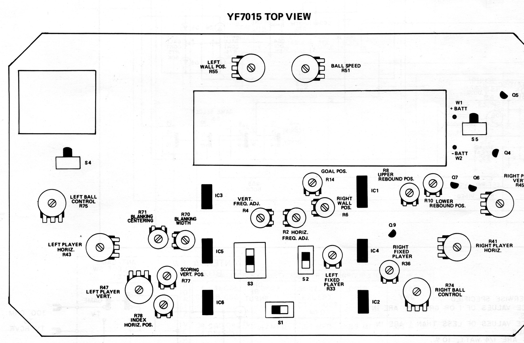
"YF7015 Top View" from Magnavox Service Manual No. 6503, page 6503-3: the Odyssey 200 board outline with the positions of the adjustment potentiometers, including the fixed player controls R33 and R36, the player and ball controls, switches S1 to S5, IC1 to IC6, Q9 and battery terminals W1 and W2. Rendered from the hosted scan at 2000 px wide.
Source
[edit | edit source]

File:Magnavox Odyssey 100 and 200 Service Manual 6503.pdf, page 3, from Internet Archive item MagnavoxOdyssey (retrieved 2026-10-19).
Author
[edit | edit source]

The Magnavox Company, Service Department.
Licence
[edit | edit source]

Copyright 1976 The Magnavox Company. Hosted for preservation and repair reference, with the source cited.
File history
Click on a date/time to view the file as it appeared at that time.
| Date/Time | Thumbnail | Dimensions | User | Comment | |
|---|---|---|---|---|---|
| current | 08:41, 19 October 2026 | | 2,000 × 1,312 (347 KB) | Josh (talk | contribs) | Upload for the Magnavox Odyssey 100 and 200 pages; source and licence on the file page |
You cannot overwrite this file.
File usage
The following 2 pages use this file:
