

File:Magnavox Odyssey 2 power supply schematic (SM 6510).png

Summary
[edit | edit source]

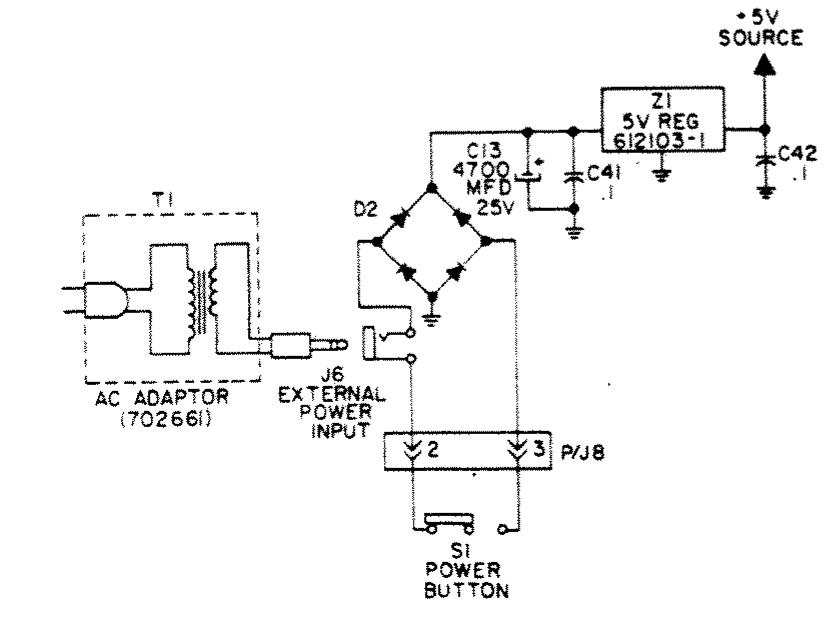
The power supply section of the Odyssey² schematic diagram in Magnavox Service Manual No. 6510, page 6510-7: AC adaptor 702661 (transformer T1), the external power input J6, the power button S1 on P/J8, the bridge rectifier D2, the 4700 µF 25 V capacitor C13, C41, the 5 V regulator Z1 (612103-1) and C42 on the +5 V source. Cropped from a 300 dpi render of the hosted scan.
Source
[edit | edit source]

File:Magnavox Odyssey 2 Service Manual 6510.pdf, PDF page 9, from Internet Archive item o2-svc (retrieved 2026-10-19).
Author
[edit | edit source]

Magnavox Consumer Electronics Company, Service Department.
Licence
[edit | edit source]

Copyright 1979 Magnavox Consumer Electronics Co. Hosted for preservation and repair reference, with the source cited.
File history
Click on a date/time to view the file as it appeared at that time.
| Date/Time | Thumbnail | Dimensions | User | Comment | |
|---|---|---|---|---|---|
| current | 22:45, 19 October 2026 | | 828 × 643 (35 KB) | Josh (talk | contribs) | Upload for the Odyssey² pages; source and licence on the file page |
You cannot overwrite this file.
File usage
The following 3 pages use this file:
