

File:Multimeter set to diode and continuity test (SparkFun).jpg
Size of this preview: 600 × 600 pixels. Other resolution: 1,000 × 1,000 pixels.

Original file (1,000 × 1,000 pixels, file size: 919 KB, MIME type: image/jpeg)
Summary
[edit | edit source]

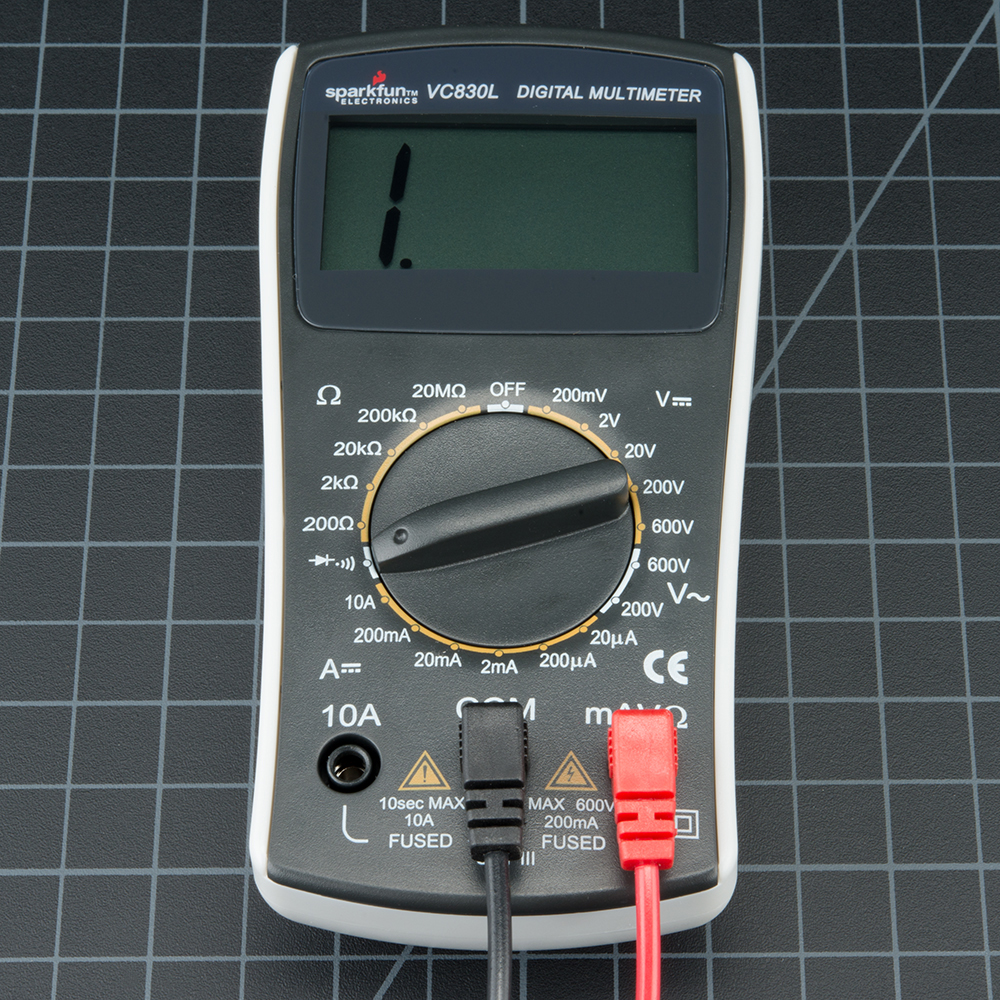
A SparkFun VC830L digital multimeter with its dial set to the combined diode and continuity position (the diode symbol with sound waves). The display shows "1", the meter's open-circuit reading. Used on Continuity Testing and Signal Tracing.
Source
[edit | edit source]

SparkFun Electronics, "How to Use a Multimeter", section "Continuity", image 01_Multimeter_Tutorial-09.jpg (retrieved 2026-10-25).
Author
[edit | edit source]

SparkFun Electronics.
Licence
[edit | edit source]

Creative Commons Attribution-ShareAlike 4.0 (CC BY-SA 4.0), as stated for SparkFun tutorials: https://creativecommons.org/licenses/by-sa/4.0/
File history
Click on a date/time to view the file as it appeared at that time.
| Date/Time | Thumbnail | Dimensions | User | Comment | |
|---|---|---|---|---|---|
| current | 14:47, 25 October 2026 | | 1,000 × 1,000 (919 KB) | Josh (talk | contribs) | Upload for repair-technique page |
You cannot overwrite this file.
File usage
The following page uses this file:
