

File:NES controller schematic (NOA workbook).png

Summary
[edit | edit source]

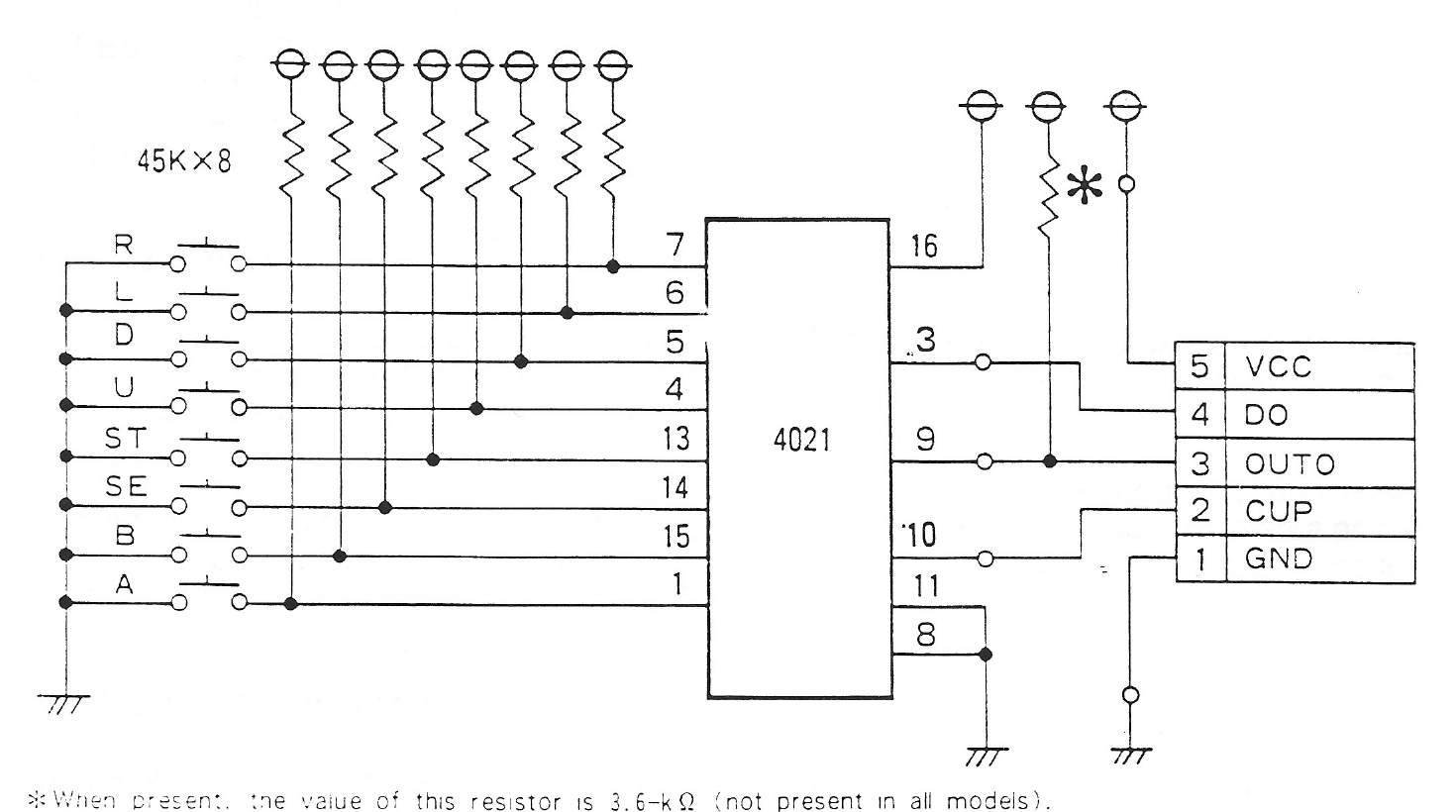
Nintendo's schematic of the NES standard controller PCB: eight button contacts pulled up by 45 kilohm resistors to the parallel inputs of a 4021 shift register, and the five-way cable connector (1 GND, 2 CUP, 3 OUT0, 4 DO, 5 VCC). The footnote gives an optional 3.6 kilohm resistor not fitted to all models. Cropped to leave out a technician's handwritten notes on the page.
Source
[edit | edit source]

Nintendo of America, NOA Independent Servicer Technical Training Workbook, Rev. 11/90, hosted here as File:NES WCS HQ.pdf (described on NOA Independent Servicer Technical Training Workbook), page 10 (PDF page 16). Rendered and cropped from the PDF on 25 October 2026.
Author
[edit | edit source]

Nintendo of America Inc.
Licence
[edit | edit source]

Copyright Nintendo of America Inc. Not freely licensed. Hosted for preservation and repair reference, with the source cited.
File history
Click on a date/time to view the file as it appeared at that time.
| Date/Time | Thumbnail | Dimensions | User | Comment | |
|---|---|---|---|---|---|
| current | 09:03, 25 October 2026 | | 1,470 × 820 (171 KB) | Josh (talk | contribs) | Upload for NES repair guides; source and licence on the description page |
You cannot overwrite this file.
File usage
The following page uses this file:
