

File:Panasonic FS-A1GT main board power supply section (Technical Guide).jpg

Summary
[edit | edit source]

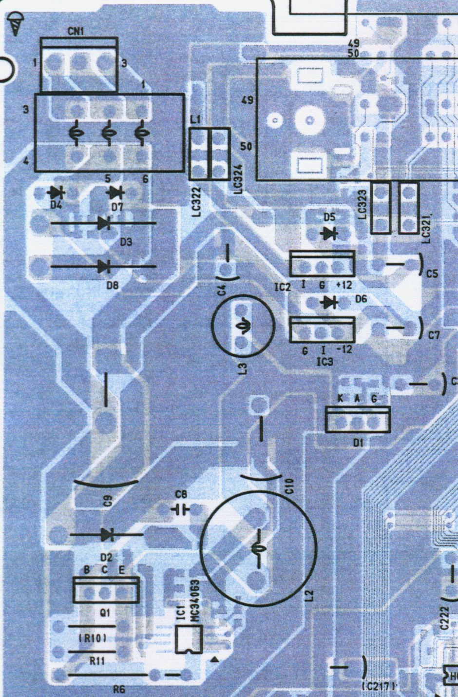
Front left corner of the Panasonic FS-A1GT main board (component side), from the main board layout drawing on printed pages 35 and 36 of Panasonic's FS-A1GT Technical Guide No. 107 (February 1992). It shows the power supply section: the transformer connector CN1, rectifier diodes D3, D4, D7 and D8, the reservoir capacitor C9, the DC/DC converter IC1 (MC34063) with its switching transistor Q1, diode D2, inductors L2 and L3 and output capacitor C10, the crowbar thyristor D1, the +12 V regulator IC2 and -12 V regulator IC3 with C4, C5 and C7, and the start of cartridge connector pins 49 and 50.
Source
[edit | edit source]

Cropped from PDF page 34 of File:Panasonic FS-A1GT Technical Guide No. 107.pdf, itself from Internet Archive item panasonicturborgtsm, https://archive.org/details/panasonicturborgtsm (retrieved 2026-10-21).
Author
[edit | edit source]

Matsushita Electric Industrial Co., Ltd. (Panasonic).
Licence
[edit | edit source]

Copyright Matsushita Electric Industrial Co., Ltd. Hosted for repair reference, with the source cited.
File history
Click on a date/time to view the file as it appeared at that time.
| Date/Time | Thumbnail | Dimensions | User | Comment | |
|---|---|---|---|---|---|
| current | 10:56, 21 October 2026 | | 940 × 1,430 (419 KB) | Josh (talk | contribs) | Power supply area of the FS-A1GT main board layout, from the Technical Guide |
You cannot overwrite this file.
File usage
The following 3 pages use this file:
