

File:Phihong PSM-5341 schematic, outputs and regulation (Mega STE copy).png

Summary
[edit | edit source]

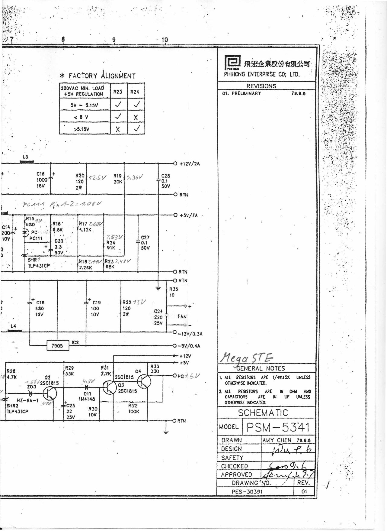
The right half of Phihong's schematic of the PSM-5341 power supply (drawing PES-30391, revision 01), from the copy marked "Mega STE": the +12 V/2 A, +5 V/7 A, −12 V/0.3 A and −5 V/0.4 A outputs (the −5 V from a 7905 regulator, IC2), the TL431 regulator SHR1 and optocoupler PC111 that set the +5 V output with R17, R18, R23 and R24, the power-good circuit (Q2–Q4) and the fan output. A "Factory alignment" table gives which of R23 and R24 to fit, with the supply at 220 V AC and minimum load, for a +5 V output below 5 V, between 5 and 5.15 V, or above 5.15 V. Handwritten notes give measured voltages. Rendered from page 7 of File:Phihong PSM-5341 Power Supply Specification and Schematic.pdf.
Source
[edit | edit source]

File:Phihong PSM-5341 Power Supply Specification and Schematic.pdf, page 7 (rendered 2026-10-25), from exxos's copy at https://www.exxosforum.co.uk/atari/last/psu/index.htm.
Author
[edit | edit source]

Phihong Enterprise Co., Ltd.; handwritten notes by an unknown owner of the copy.
Licence
[edit | edit source]

Copyright Phihong Enterprise Co., Ltd. Hosted for preservation and repair reference, with the source cited.
File history
Click on a date/time to view the file as it appeared at that time.
| Date/Time | Thumbnail | Dimensions | User | Comment | |
|---|---|---|---|---|---|
| current | 11:49, 25 October 2026 | | 1,282 × 1,757 (478 KB) | Josh (talk | contribs) | Phihong PSM-5341 schematic half for power supply repair guide |
You cannot overwrite this file.
File usage
The following page uses this file:
