

File:Philips NMS 8250 power supply board layout (service manual).png

Summary
[edit | edit source]

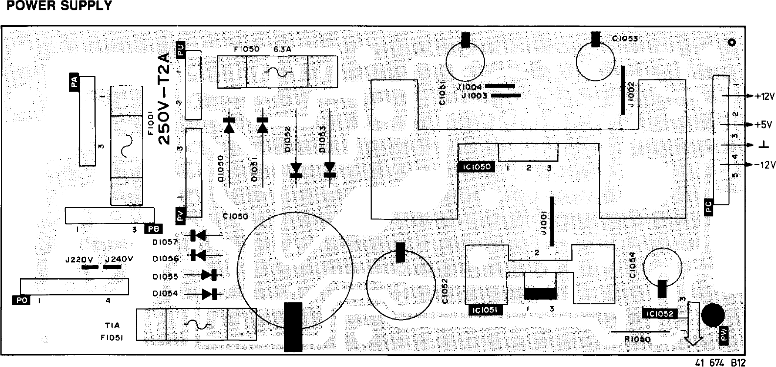
Component layout of the power supply board U101 of the Philips NMS 8250 and NMS 8255 (drawing 41 674 B12): fuses F1001 (250 V, T 2 A), F1050 (6.3 A) and F1051 (T 1 A), rectifiers D1050 to D1057, regulators IC1050 to IC1052, electrolytic capacitors C1050 to C1054, resistor R1050, the mains voltage links J220V and J240V, and the output connector PC (pin 1 +12 V, pin 2 +5 V, pin 3 ground, pin 4 −12 V). Rendered from File:Philips NMS 8250 and NMS 8255 Service Manual.pdf, PDF page 32.
Source
[edit | edit source]

Philips service manual NMS8250/NMS8255, via the MSX Archive scan (https://www.msxarchive.nl/pub/msx/docs/service_manuals/philipsnms825055sm.pdf), retrieved 2026-10-21.
Author
[edit | edit source]

Philips Consumer Electronics.
Licence
[edit | edit source]

Copyright Philips. Hosted for repair reference, with the source cited.
File history
Click on a date/time to view the file as it appeared at that time.
| Date/Time | Thumbnail | Dimensions | User | Comment | |
|---|---|---|---|---|---|
| current | 12:18, 21 October 2026 | | 1,585 × 749 (83 KB) | Josh (talk | contribs) | Upload for the NMS 8250 capacitor guide; source and licence on the file page |
You cannot overwrite this file.
File usage
The following 3 pages use this file:
