

File:Philips Odyssey 2100 board layout (CS43618).jpg

Summary
[edit | edit source]

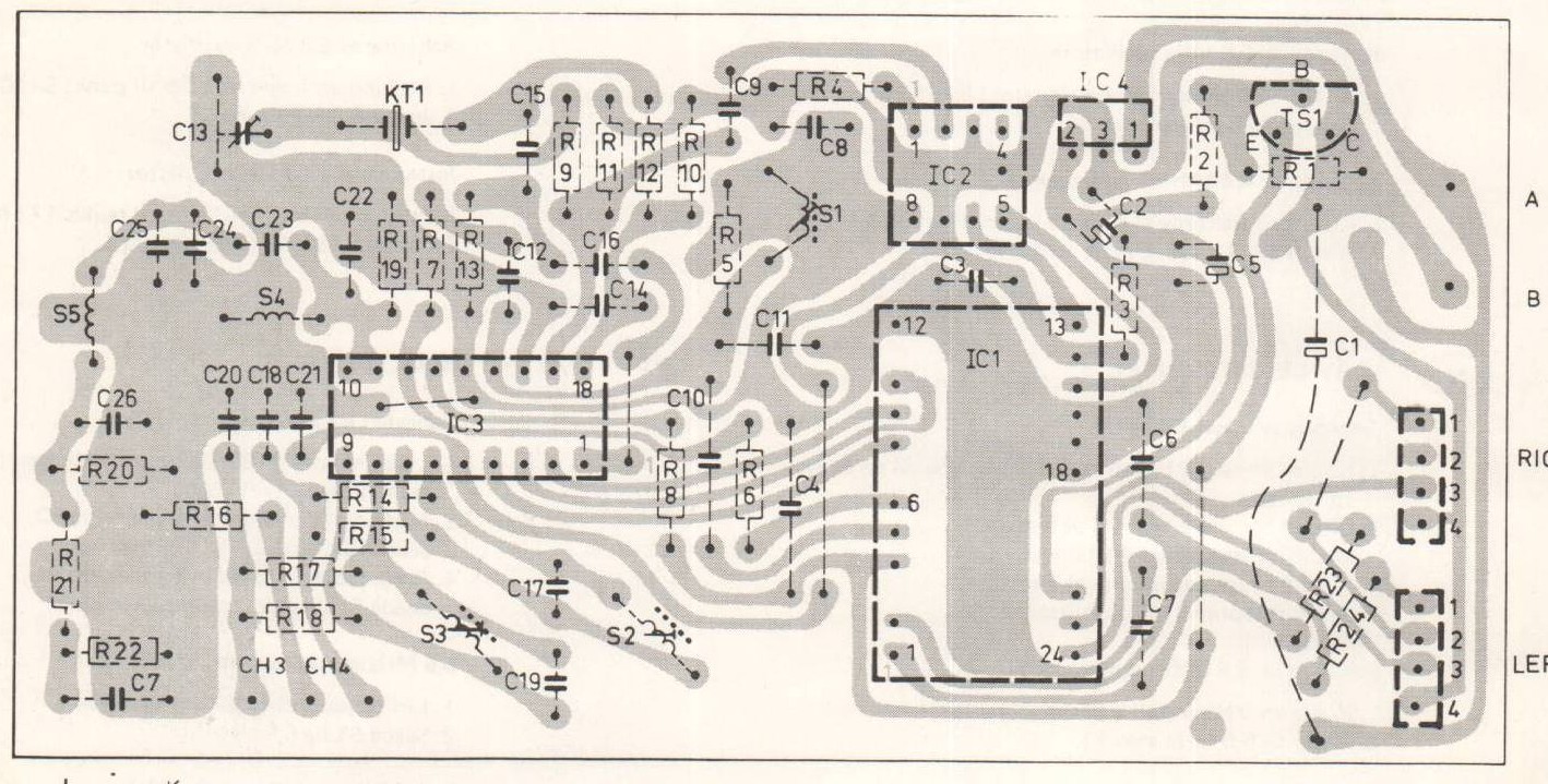
Philips's drawing of the Odyssey 2100 (type G7513) printed circuit board, from page 3 of the service manual CS43618, with the position of every part: IC1 to IC4, the electrolytic capacitors C1, C2 and C5, the trimmer C13 and crystal KT1, the coils S1 to S5, the transistor TS1, the supply terminals A and B and the RIGHT and LEFT controller connectors.
Source
[edit | edit source]

Internet Archive item MagnavoxOdyssey, file "Philips Odyssey 2100 (model G7513) Service Manual.pdf" (retrieved 2026-10-20). The item description credits the scan to Wil Manshande of www.freeservicemanuals.info; each page carries that site's stamp.
Author
[edit | edit source]

Philips (service documentation).
Licence
[edit | edit source]

Copyright Philips. Hosted for preservation and repair reference, with the source cited.
File history
Click on a date/time to view the file as it appeared at that time.
| Date/Time | Thumbnail | Dimensions | User | Comment | |
|---|---|---|---|---|---|
| current | 23:47, 20 October 2026 | | 1,418 × 719 (314 KB) | Josh (talk | contribs) | Board layout from Philips service manual CS43618 |
You cannot overwrite this file.
File usage
The following page uses this file:
