

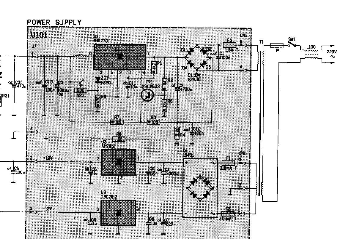
File:Philips VG-8020-00 power supply circuit diagram (service manual).png
Size of this preview: 800 × 559 pixels. Other resolution: 1,154 × 807 pixels.

Original file (1,154 × 807 pixels, file size: 90 KB, MIME type: image/png)
Summary
[edit | edit source]

Circuit diagram of the power supply module U101 (STK770 +5 V regulator with 2SC2603 pass transistor, AN7812 and JRC7912 for +12 V and -12 V, fuses F1 to F3, mains switch SW1 and line filter L100) of the Philips VG 8020/00, with the power LED circuit and C35 on the main board side of connector J7. Cropped from page 22 of the service manual 4822 727 15228. Some values are faint on the scan.
Source
[edit | edit source]

Rendered from File:Philips VG-8020-00 Service Manual 4822 727 15228.pdf, page 22.
Author
[edit | edit source]

Philips Service Consumer Electronics.
Licence
[edit | edit source]

Copyright Philips. Hosted for preservation and repair reference, with the source cited.
File history
Click on a date/time to view the file as it appeared at that time.
| Date/Time | Thumbnail | Dimensions | User | Comment | |
|---|---|---|---|---|---|
| current | 11:18, 21 October 2026 | | 1,154 × 807 (90 KB) | Josh (talk | contribs) | VG 8020/00 power supply diagram from the service manual |
You cannot overwrite this file.
File usage
The following page uses this file:
