

File:Philips Videopac G7000 UHF modulator schematic (SM CS 75 068).png
Size of this preview: 800 × 596 pixels. Other resolution: 1,650 × 1,230 pixels.

Original file (1,650 × 1,230 pixels, file size: 662 KB, MIME type: image/png)
Summary
[edit | edit source]

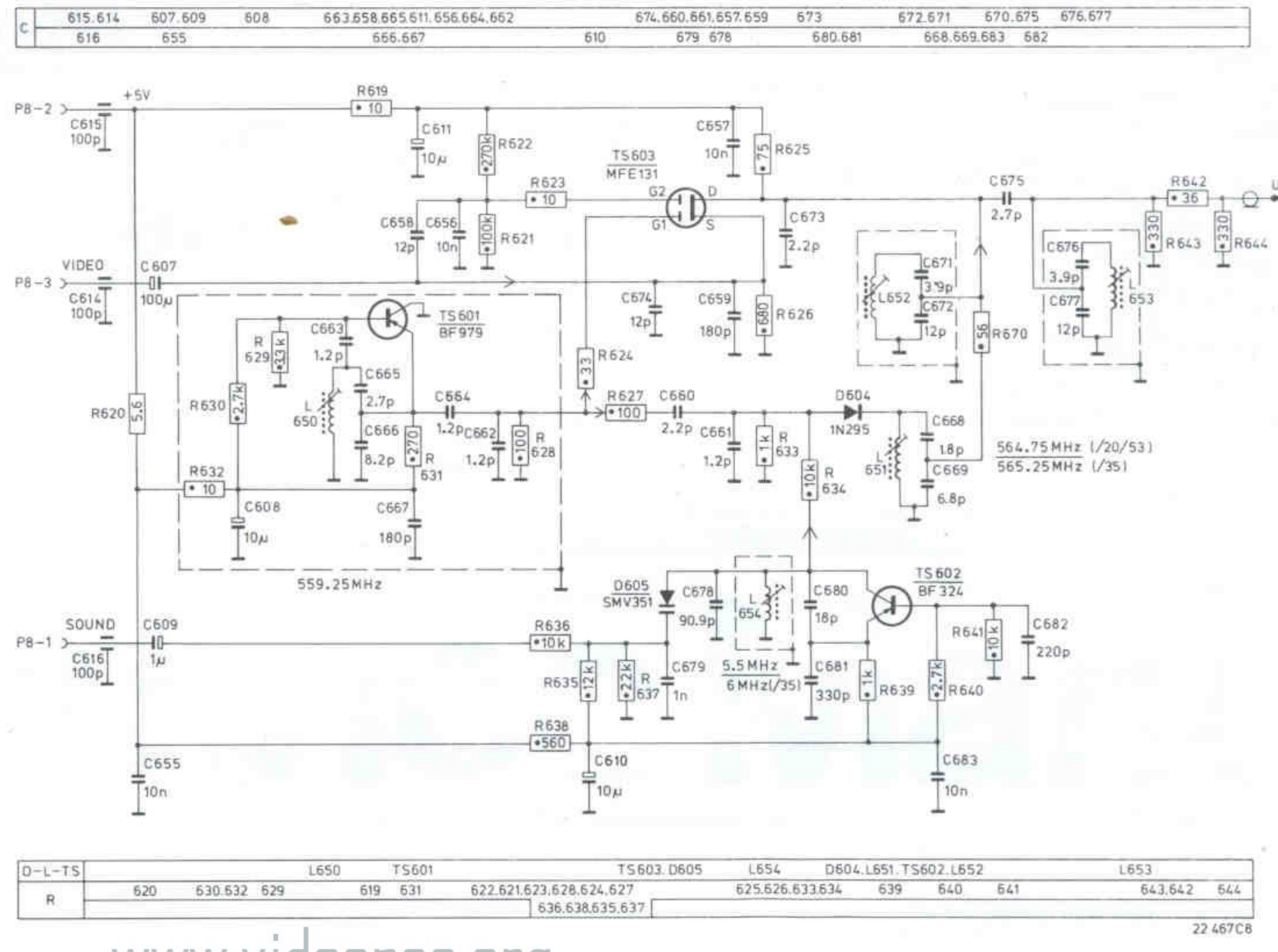
Circuit diagram of the G7000/20/35/53 UHF modulator U100 (drawing 22 467 C8): inputs P8-1 sound, P8-2 +5 V and P8-3 video; the 559.25 MHz oscillator TS601 (BF979) with L650; the sound oscillator TS602 (BF324) with varicap D605 (SMV351) and L654, 5.5 MHz or 6 MHz on the /35; the MFE131 modulator TS603; and the output filters L652 and L653 (564.75 MHz on /20 and /53, 565.25 MHz on /35).
Source
[edit | edit source]

Cropped from page 3 of File:Philips Videopac G7000 Service Manual CS 75 068.pdf.
Author
[edit | edit source]

Philips
Licence
[edit | edit source]

Copyright Philips. Reproduced from the service manual for repair reference.
File history
Click on a date/time to view the file as it appeared at that time.
| Date/Time | Thumbnail | Dimensions | User | Comment | |
|---|---|---|---|---|---|
| current | 00:50, 21 October 2026 | | 1,650 × 1,230 (662 KB) | Josh (talk | contribs) | Upload Philips Videopac G7000 material for the G7000 pages |
You cannot overwrite this file.
File usage
The following 2 pages use this file:
