

File:Philips Videopac G7000 power supply schematic (SM CS 61 799).png
Size of this preview: 630 × 530 pixels.
Original file (630 × 530 pixels, file size: 29 KB, MIME type: image/png)
Summary
[edit | edit source]

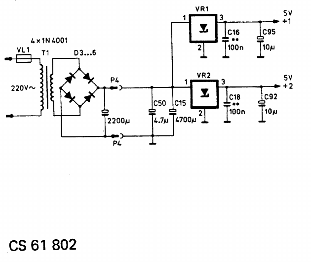
The power supply section of the G 7000 circuit diagram CS 61 802 in service manual CS 61 799: fuse VL1, transformer T1 for 220 V, bridge D3 to D6 (4 x 1N4001) and a 2200 µF capacitor in the power unit; connector P4, C50 4.7 µF, C15 4700 µF and the two regulators VR1 and VR2 with C16, C18 (100 nF) and C95, C92 (10 µF) on the main board.
Source
[edit | edit source]

Cropped from page 5 of File:Philips Videopac G7000 Service Manual CS 61 799.pdf.
Author
[edit | edit source]

Philips
Licence
[edit | edit source]

Copyright Philips. Reproduced from the service manual for repair reference.
File history
Click on a date/time to view the file as it appeared at that time.
| Date/Time | Thumbnail | Dimensions | User | Comment | |
|---|---|---|---|---|---|
| current | 00:50, 21 October 2026 | | 630 × 530 (29 KB) | Josh (talk | contribs) | Upload Philips Videopac G7000 material for the G7000 pages |
You cannot overwrite this file.
File usage
The following 5 pages use this file:

