

File:Plated through hole repair cross-sections (diagram).png

Summary
[edit | edit source]

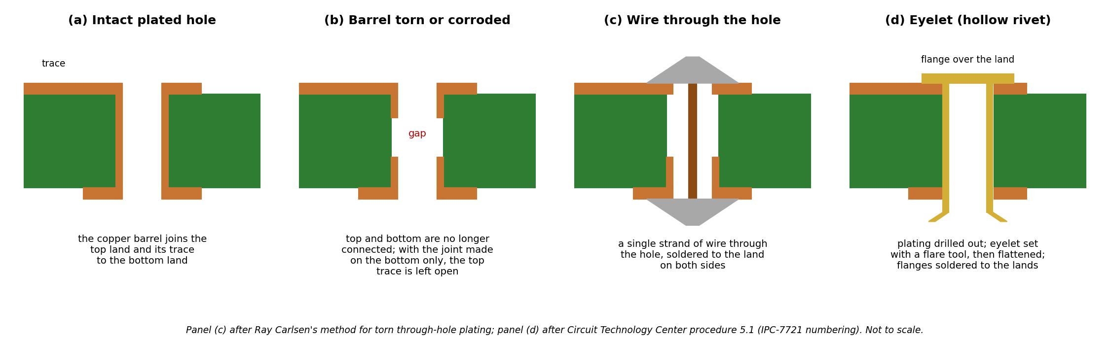
Four cross-sections of a plated through hole in a two-layer board: (a) intact, with the copper barrel joining the top land and its trace to the bottom land; (b) with the barrel torn or corroded, so the top trace is no longer connected; (c) repaired with a single strand of wire through the hole, soldered to the lands on both sides; (d) repaired with an eyelet whose flange sits on the top land and whose barrel is flared and flattened underneath. Not to scale.
Source
[edit | edit source]

Drawn for this wiki (2026-10-25). Panel (c) follows Ray Carlsen, "Replacing IC chips in Commodore equipment"; panel (d) follows Circuit Technology Center, procedure 5.1, Plated Hole Repair, No Inner Layer Connection.
Author
[edit | edit source]

RetroTechCollection wiki.
Licence
[edit | edit source]

Drawn for this wiki and released under Creative Commons Attribution-ShareAlike 4.0.
File history
Click on a date/time to view the file as it appeared at that time.
| Date/Time | Thumbnail | Dimensions | User | Comment | |
|---|---|---|---|---|---|
| current | 14:49, 25 October 2026 | | 2,250 × 690 (100 KB) | Josh (talk | contribs) | Upload for the PCB repair technique pages |
You cannot overwrite this file.
File usage
The following page uses this file:
