

File:Screw boss and heat-set insert diagram.png

Summary
[edit | edit source]

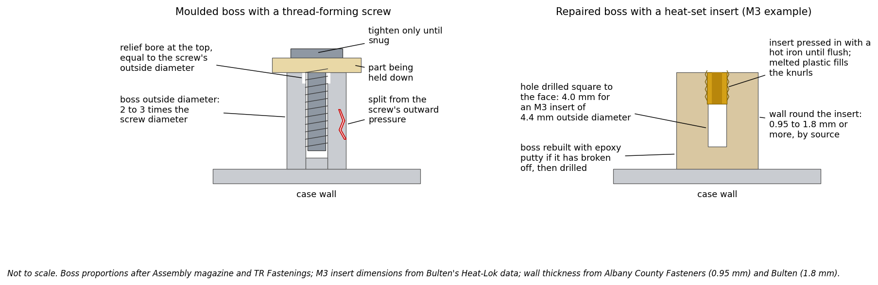
Two-panel cross-section diagram of plastic screw bosses. Left: a moulded boss holding a thread-forming screw, with the boss outside diameter of two to three times the screw diameter, a relief bore at the top equal to the screw's outside diameter, the part being clamped, and a split in the boss wall caused by the screw's outward pressure. Right: a boss rebuilt in epoxy putty and drilled for a heat-set brass insert, with the M3 example dimensions (4.0 mm hole, 4.4 mm insert) and the minimum wall thickness round the insert (0.95 mm to 1.8 mm depending on the source). Not to scale.
Source
[edit | edit source]

Drawn for this wiki in October 2026 from: Assembly magazine, "Beware the boss", https://www.assemblymag.com/articles/83662-beware-the-boss (boss diameter, relief bore, outward force); TR Fastenings, "Plas-Fix 45 installation", https://www.trfastenings.com/Knowledge-Base/Fasteners-for-Plastic/Plas-Fix-45-installation (boss diameter 2.5 to 3 times the pilot hole); Bulten, Heat-Lok Inserts & Studs data sheet, https://bulten.com/media/zx4cucuw/heat-lok-cleaned.pdf (M3 insert 4.4 mm, 4.0 mm hole, 1.8 mm wall); Albany County Fasteners, Heat-Set Insert Specifications, https://www.albanycountyfasteners.com/media/64/3d/5a/1764619189/heat-set-insert-specs.pdf (0.95 mm wall); J-B Weld PlasticWeld product page (epoxy putty can be drilled). All retrieved 2026-10-25. Used on Plastic Case and Screw Post Repair.
Author
[edit | edit source]

RetroTechCollection wiki.
Licence
[edit | edit source]

Released under CC BY-SA 4.0 (https://creativecommons.org/licenses/by-sa/4.0/).
File history
Click on a date/time to view the file as it appeared at that time.
| Date/Time | Thumbnail | Dimensions | User | Comment | |
|---|---|---|---|---|---|
| current | 15:34, 25 October 2026 | | 1,807 × 587 (128 KB) | Josh (talk | contribs) | Upload diagram drawn for the repair-technique pages |
You cannot overwrite this file.
File usage
The following page uses this file:
