

File:Sega 32X service bulletin 014 Mega Drive VA5 VA6 drawing.png

Summary
[edit | edit source]

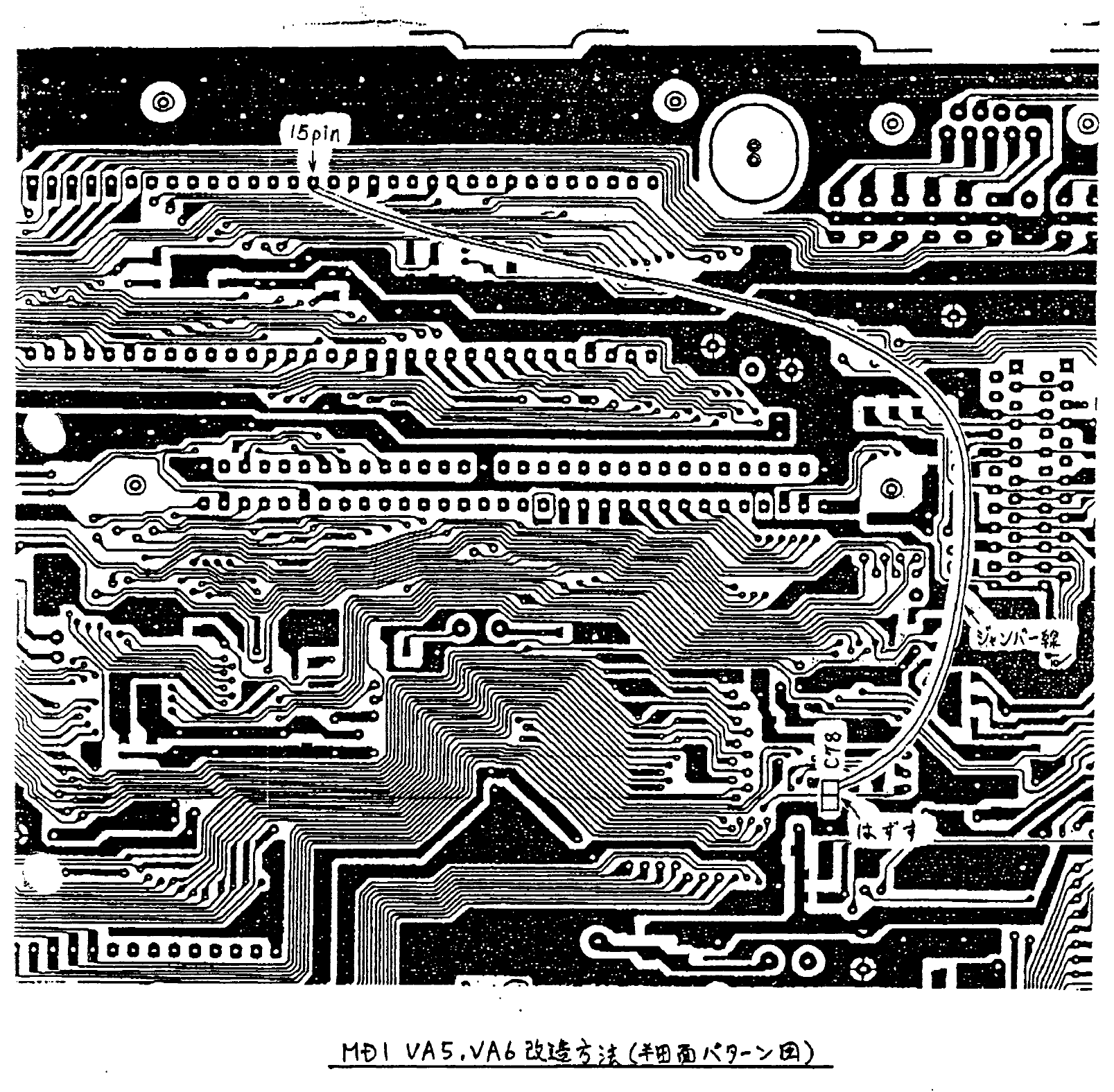
Drawing attached to Sega Quality Assurance Division service bulletin 014 (12 April 1995): solder-side track pattern of the Mega Drive (Model 1) VA5 and VA6 board, showing C78 marked for removal and a jumper wire from the C78 pad to the pin marked "15pin" of the 68000. The Japanese caption reads, in translation, "MD1 VA5, VA6 modification method (solder side pattern diagram)".
Source
[edit | edit source]

Rendered at 200 dpi from page 8 of File:Sega 32X Service Builletins.pdf (see Sega 32X Service Bulletins).
Author
[edit | edit source]

Sega Enterprises, Ltd., Quality Assurance Division.
Licence
[edit | edit source]

Copyright Sega Enterprises, Ltd. Hosted for preservation and repair reference, with the source cited.
File history
Click on a date/time to view the file as it appeared at that time.
| Date/Time | Thumbnail | Dimensions | User | Comment | |
|---|---|---|---|---|---|
| current | 09:01, 25 October 2026 | | 1,607 × 1,575 (203 KB) | Josh (talk | contribs) | Upload for repair guide; source and licence on file page |
You cannot overwrite this file.
File usage
The following page uses this file:
