

File:Sega Master System (Model 1) video output schematic.png

Summary
[edit | edit source]

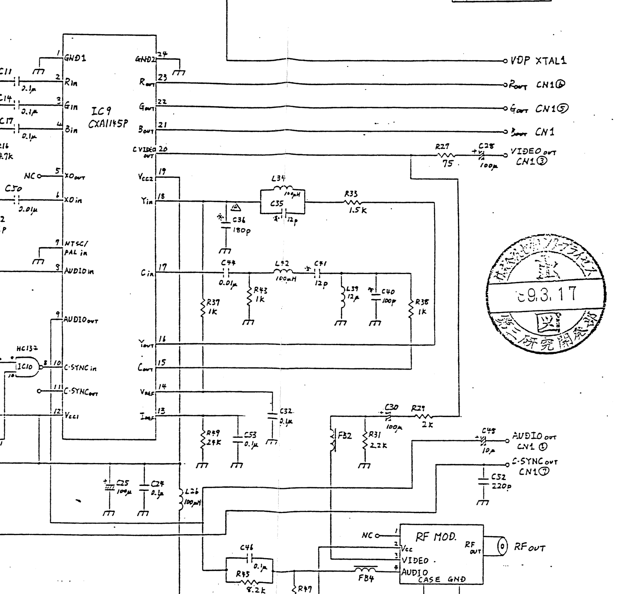
Crop of the video encoder section of Sega's schematic "IC Board PB PAL VA1" (171-5534), sheet 2: IC9 (drawn as a CXA1145P) with its RGB inputs, the composite video output on pin 20 through R27 (75 Ω) and C28 (100 µF) to CN1 pin 3, the branch through R29 and C30 to the RF modulator video input, the RGB outputs to CN1 pins 6, 5 and 8, and the audio and sync outputs.
Source
[edit | edit source]

Sega Enterprises, Ltd., Sega Master System Service Manual (Power Base, PAL), schematic p. 14 (PDF p. 15), hosted on this wiki as File:Sega Master System (Model 1) Service Manual.pdf
Author
[edit | edit source]

Sega Enterprises, Ltd.
Licence
[edit | edit source]

Copyright Sega Enterprises, Ltd. Hosted for preservation and repair reference, with the source cited.
File history
Click on a date/time to view the file as it appeared at that time.
| Date/Time | Thumbnail | Dimensions | User | Comment | |
|---|---|---|---|---|---|
| current | 10:57, 25 October 2026 | | 2,000 × 1,907 (298 KB) | Josh (talk | contribs) | Upload for Master System repair guides |
You cannot overwrite this file.
File usage
The following page uses this file:
