

File:Sega Master System II controller port schematic.png

Summary
[edit | edit source]

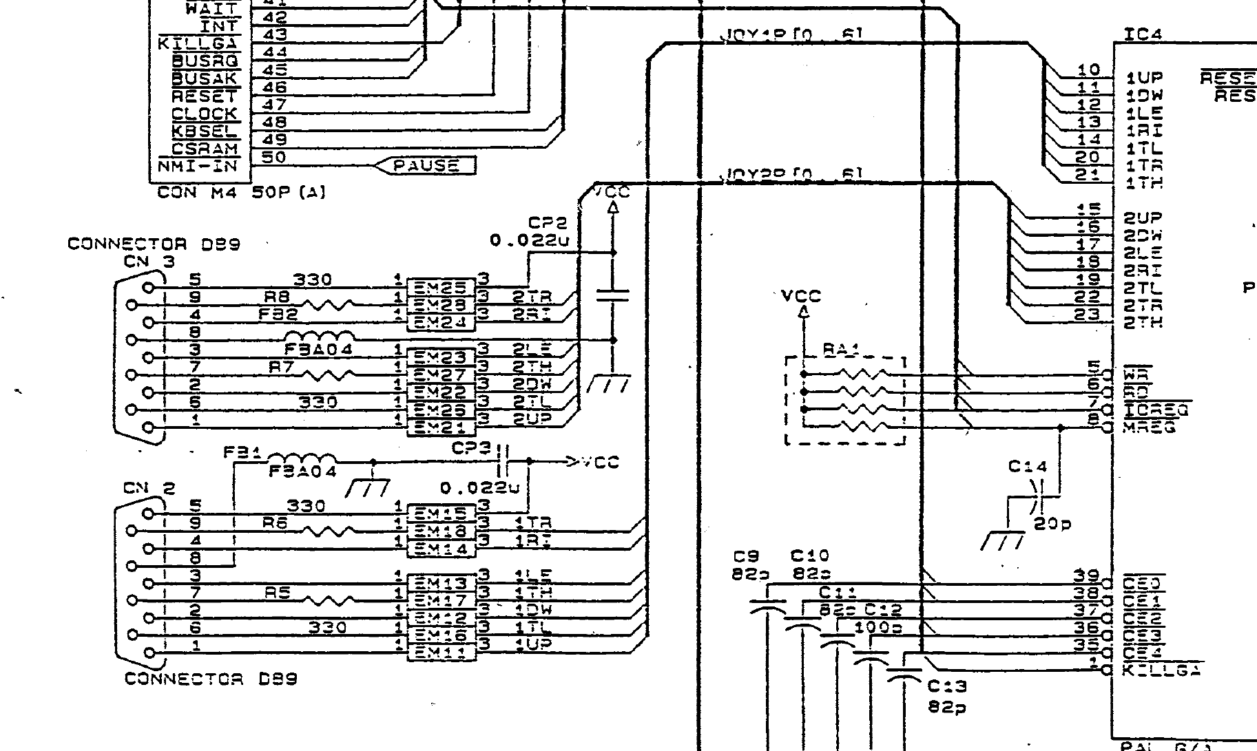
Crop of Sega's Sega Master System II PAL schematic, sheet 2, showing the controller sockets CN2 (player 1) and CN3 (player 2), the EMI filters EM11 to EM18 and EM21 to EM28, the 330 Ω resistors R5 to R8 in the TH and TR lines, beads FB1 and FB2 in the ground lines, decoupling capacitors CP2 and CP3, and the joypad inputs of the gate array IC4 (pins 10 to 14, 20 and 21 for player 1; 15 to 19, 22 and 23 for player 2).
Source
[edit | edit source]

Sega Enterprises, Ltd., Sega Master System II Service Manual, April 1991, schematic diagram for the PAL version, "IC BD M4JR PAL" 171-5922A, sheet 2 of 3 (p. 12, PDF p. 19), hosted on this wiki as File:Sega Master System II Service Manual April 1991.pdf. Cropped and converted to greyscale; nothing else changed.
Author
[edit | edit source]

Sega Enterprises, Ltd.
Licence
[edit | edit source]

Copyright Sega Enterprises, Ltd. Hosted for preservation and repair reference, with the source cited.
File history
Click on a date/time to view the file as it appeared at that time.
| Date/Time | Thumbnail | Dimensions | User | Comment | |
|---|---|---|---|---|---|
| current | 11:12, 25 October 2026 | | 1,825 × 1,091 (69 KB) | Josh (talk | contribs) | Upload for Master System II repair guides |
You cannot overwrite this file.
File usage
The following page uses this file:
