

File:Sega Mega Drive M5 PAL VA4 power input schematic.png

Summary
[edit | edit source]

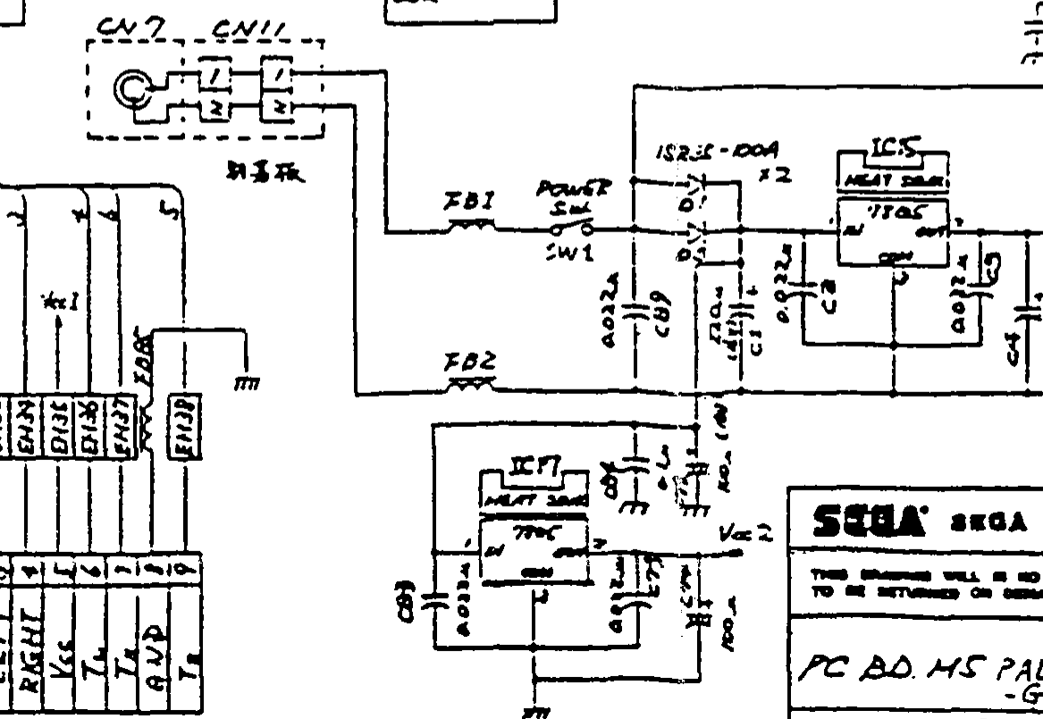
Crop of Sega's schematic "PC BD M5 PAL VA4 MAIN -G Version" (sheet 1) showing the Mega Drive (Model 1) power input: the DC jack (CN7, on the sub board) and its lead to CN11, ferrite beads FB1 and FB2, the power switch SW1, the two 1SR35-100A diodes, the reservoir capacitor C1, and the two 7805 regulators IC15 (Vcc1) and IC17 (Vcc2), each drawn with its heat sink. The schematic is hand-lettered.
Source
[edit | edit source]

Rendered at 300 dpi from Sega's Mega Drive Maintenance Manual, PAL-G, August 1992, Rev. A, section 9, PDF page 65, hosted here as File:Mega Drive Maintenance Manual - PAL-G, August, 1992, Rev. A.pdf (see Mega Drive Maintenance Manual - PAL-G, August, 1992, Rev. A), and cropped.
Author
[edit | edit source]

Sega Enterprises, Ltd.
Licence
[edit | edit source]

Copyright Sega Enterprises, Ltd. Hosted for preservation and repair reference, with the source cited.
File history
Click on a date/time to view the file as it appeared at that time.
| Date/Time | Thumbnail | Dimensions | User | Comment | |
|---|---|---|---|---|---|
| current | 09:01, 25 October 2026 | | 1,167 × 805 (49 KB) | Josh (talk | contribs) | Upload for repair guide; source and licence on file page |
You cannot overwrite this file.
File usage
The following page uses this file:
