

File:Sega SG-1000 joystick circuit (Enri).png
Summary
[edit | edit source]

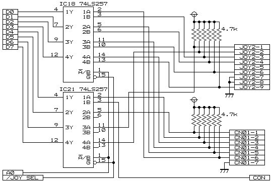
Enri's redrawn circuit of the Sega SG-1000's joystick inputs: the two 74LS257 multiplexers IC18 and IC21, enabled by /JOY SEL and switched by A0, reading the data bus D0 to D7 from the second joystick socket (JOY2, pins 1 to 9) and the seven-pin header for the fixed first joystick (CN01, pins 1 to 7). Each input has a 4.7 kΩ pull-up resistor to 5 V; JOY2 pins 7 and 8 and CN01 pin 7 go to ground, and JOY2 pin 5 is not connected. Drawn by Enri from the console; not a Sega document.
Source
[edit | edit source]

Enri's Home Page, "SEGA SG-1000", http://cmpslv3.stars.ne.jp/Sg1000/EnrSG.htm, image sgjoy.png (retrieved 2026-10-25).
Author
[edit | edit source]

Enri
Licence
[edit | edit source]

No licence is given on the source page. Copyright Enri. Hosted here, credited to its source, for repair reference.
File history
Click on a date/time to view the file as it appeared at that time.
| Date/Time | Thumbnail | Dimensions | User | Comment | |
|---|---|---|---|---|---|
| current | 11:25, 25 October 2026 | | 540 × 370 (4 KB) | Josh (talk | contribs) | Upload for the SG-1000 joystick repair guide |
You cannot overwrite this file.
File usage
The following page uses this file:
